Robot and spot welding robot with learning control function

a robot and function technology, applied in the field of robot and spot welding robots having learning control functions, can solve the problems of narrow application range, inability to measure the trajectory error and position vibration component of the arm, and inability to produce position vibration components, etc., to improve the accuracy and safety of operation of the robot mechanism unit, reduce system cost, and increase the speed of operation during learning

Active Publication Date: 2012-11-22
FANUC LTD
View PDF6 Cites 117 Cited by
  • Summary
  • Abstract
  • Description
  • Claims
  • Application Information

AI Technical Summary

Benefits of technology

[0048]A robot according to one aspect of the present invention performs processes so that the control target position of a robot mechanism unit moves on a fixed trajectory regardless of the speed change ratio. As a result of this, trajectory drift due to change of the speed change ratio is not produced, and therefore it is possible to improve the accuracy and safety of operation of the robot mechanism unit.
[0049]Furthermore, with a robot according to another aspect of the present invention, a learning control unit calculates the maximum speed change ratio that can be set in a learning operating state, and calculates a learning correction amount while changing the speed change ratio over a plurality of times until reaching the maximum speed change ratio. As a result of this, it is possible to actually increase the speed of operation during learning.
[0050]There is also an advantage that the system cost can be reduced by reducing the number of robots required to perform tasks, reducing the line space, and reducing the steps to perform. Furthermore, the number of robots to maintain can be redu

Problems solved by technology

Even if the position feedback control, speed feedback control and furthermore current feedback control are executed, when a robot is operated at high-speed, a trajectory error and a position vibration component may be produced.
Consequently, it is not possible to measure the trajectory error and position vibration component of the arm directly using a motor encoder which is provided near the motor for driving the arm.
However, there is a problem, with conventional learning control, that the range of application is narrow and usability is given not much thought.
In the case an acceleration sensor is mounted on a robot, although the trajectory/position errors can be extracted in orthogonal coordinates, there is still a problem that, in this condition, it is not possible to calculate the trajectory/position errors on each axis directly from the sensor data.
Consequently, the trajectory/vibration error data of frequency bands to be removed is also processed, posing a problem that learning control performance is deteriorated.
Furthermore, there are two difficult problems in adjusting a learning control filter.
Unless this is guara

Method used


Image

  • Robot and spot welding robot with learning control function
  • Robot and spot welding robot with learning control function
  • Robot and spot welding robot with learning control function

Examples


first embodiment

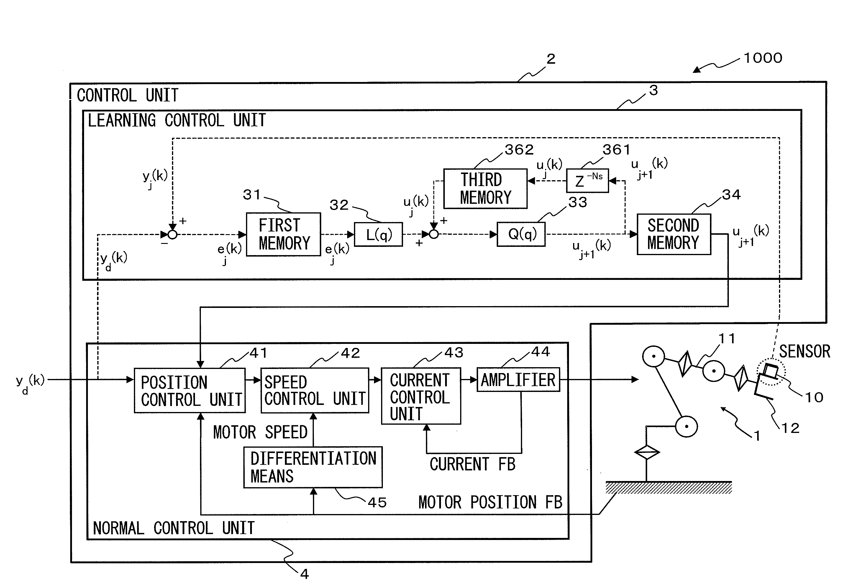
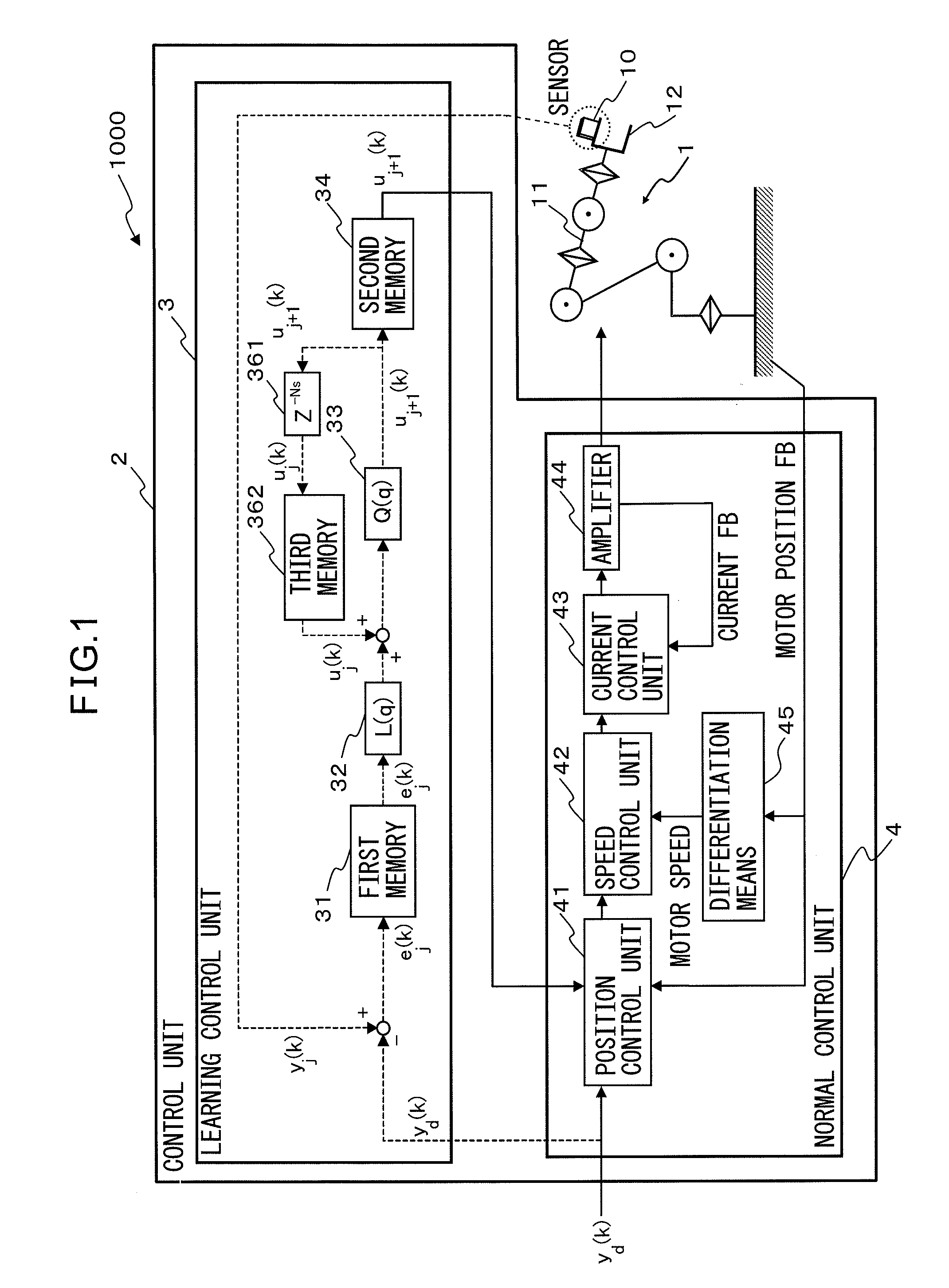
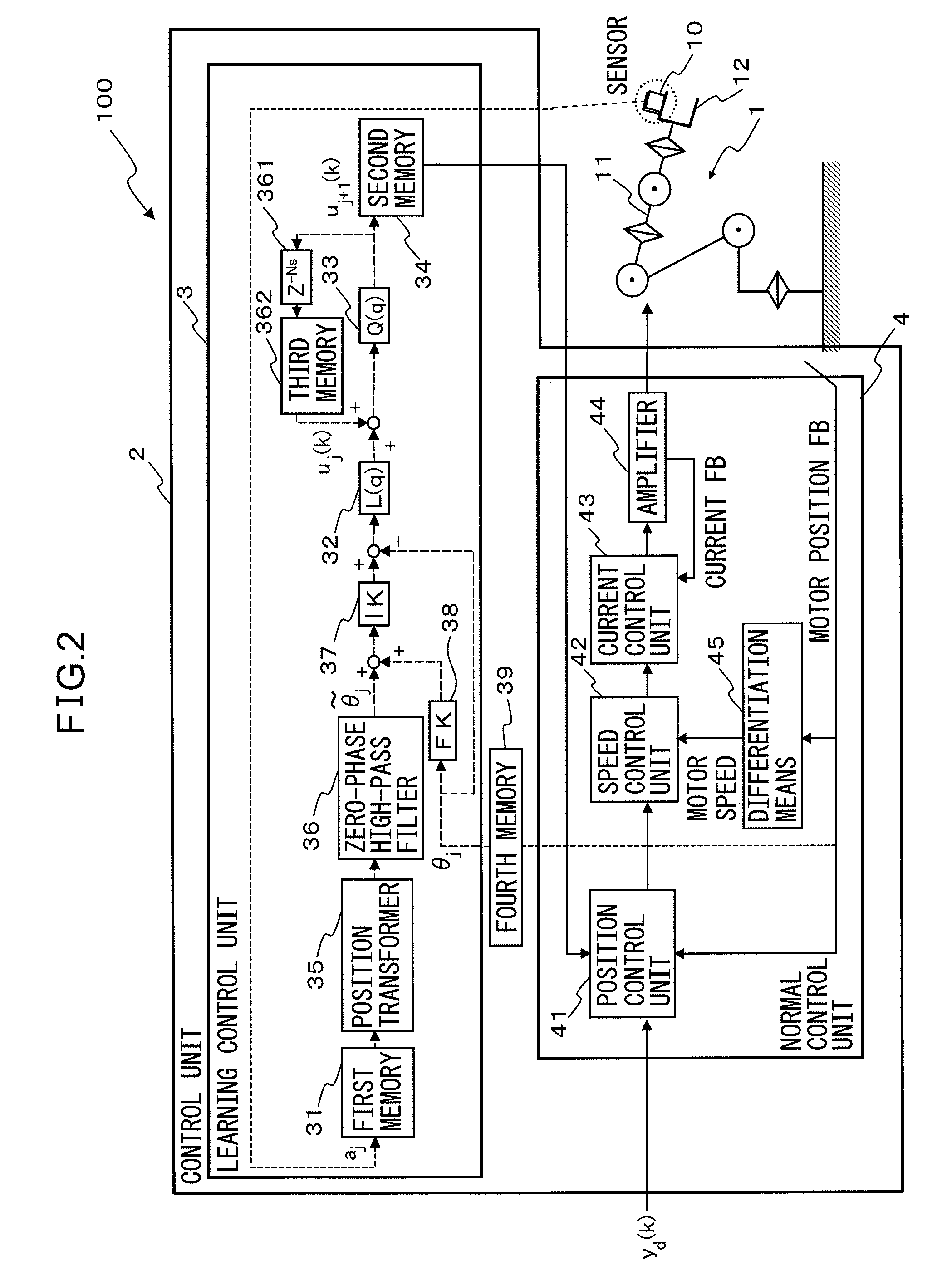
[0077]FIG. 2 is a schematic diagram of a robot 100 according to the first embodiment. The robot 100 is configured with a robot mechanism unit 1, and a control unit 2 that controls the robot mechanism unit 1. The control unit 2 has a learning control unit that executes learning control for the robot 100, and a normal control unit 4 that controls the operation of the robot mechanism unit 1 by driving the robot mechanism unit 1 directly.

[0078]The learning control unit 3 operates the robot mechanism unit according to a speed command which is given by multiplying the teaching speed designated in a task program by a speed change ratio. From a detection result of an acceleration sensor 10, the learning control unit 3 executes learning for calculating a learning correction amount uj+1(k) for making the trajectory or position of the control target of the robot mechanism unit 1 approach closer to the target trajectory or target position that is assigned to the normal control unit 4. Otherwise...

second embodiment

[0160]Next, a robot according to a second embodiment will be described. FIG. 11 shows a schematic view of the robot according to the second embodiment. In addition to the robot 100 according to the first embodiment, a robot 101 according to the second embodiment has a feature of further having a teaching control unit 50 which includes a program teaching unit 51 that stores a task program, a program executing unit 52, and an operation planning unit 53. The teaching control unit 50 teaches or corrects the position or speed in a task program.

[0161]Also, the normal control unit 4 of the robot 101 according to the second embodiment further has an anti-exception processing unit 46. This anti-exception processing unit 46 operates the robot mechanism unit 1 according to a position command based on a teaching position that is set in a task program, a learning correction amount uj+1(k) that is calculated in the learning control unit 3, and a speed command that is given by multiplying a teachi...

third embodiment

[0173]With the present embodiment, an example to increase speed of the operation of a spot welding robot will be described. First, FIG. 14 shows a perspective view of a robot mechanism unit of the spot welding robot. Also, FIG. 3 shows a configuration of the robot mechanism unit of the spot welding robot. FIG. 3A shows an overall configuration of the robot mechanism unit, and FIG. 3B shows an enlarged view of a spot welding gun (hereinafter referred to as simply “gun”) on which a sensor is mounted. The robot mechanism unit 1 is a well-known robot manipulator and has no limitations regarding its mechanism as long as the gun 12, which is the control target part and is subject to position control, can reach the positions and postures to perform tasks. The gun 12 has a pair of electrodes (namely, a counter electrode 21 and a movable electrode 22), and, by making the interval between the counter electrode 21 and the movable electrode 22 variable by making one of them movable, is able to ...


PUM

PropertyMeasurementUnit
Ratioaaaaaaaaaa
Speedaaaaaaaaaa
Accelerationaaaaaaaaaa

Abstract

A robot (100) has a robot mechanism unit (1) having a sensor (10) and a control unit (2), and the control unit (2) includes a normal control unit (4) that controls the operation of the robot mechanism unit, and a learning control unit (3) that, when the robot mechanism unit (1) is operated by a speed command that is given by multiplying a teaching speed designated in a task program by a speed change ratio, performs learning to calculate, from a detection result by the sensor (10), a learning correction amount for making the trajectory or position of the control target in the robot mechanism unit (1) approach the target trajectory or target position, or for reducing the vibration of the control target, and performs processes so that the control target position of the robot mechanism unit (1) moves along a fixed trajectory regardless of the speed change ratio.

Description

[0001]This application is a new U.S. patent application that claims benefit of JP 2011-110787 filed on May 17, 2011 and 2011-178634 filed on Aug. 17, 2011, the content of 2011-110787 and 2011-178634 is incorporated herein by reference.FIELD OF THE INVENTION[0002]The present invention relates to a robot and spot welding robot having a learning control function. More particularly, the present invention relates to a robot and spot welding robot that increase the speed of operation using a sensor attached to an arm.BACKGROUND OF THE INVENTION[0003]In a robot, the position and speed of a part to be driven by a servo-motor (hereinafter, also referred to as “motor”) are controlled. Consequently, normally, position feedback control, speed feedback control and furthermore current feedback control are executed. These controls are executed until the position and speed of the driven part match the commanded position and the commanded speed.[0004]Even if the position feedback control, speed feed...

Claims


Application Information

Patent Timeline
IPC IPC(8): G05B19/04
CPCB25J9/163B25J9/1694G05B2219/39195Y10S901/47G05B2219/45104B23K11/115Y10S901/46G05B2219/40547
Inventor INABA, KIYONORIICHINOSE, MASAKAZU
Owner FANUC LTD
Why Eureka
Try Eureka