
Electrical apparatus

Active Publication Date: 2012-11-29
GKN AEROSPACE SERVICES LTD
View PDF15 Cites 5 Cited by
  • Summary
  • Abstract
  • Description
  • Claims
  • Application Information

AI Technical Summary

Benefits of technology

[0019]For example, the laminate could be part of a lightning protection system for an aircraft, and the electrical element could be a sprayed conductive ground plane which is connectable to an aircraft earth by the ribbon connector. It is also envisaged that the present invention could find application in the automotive industry. For example, a laminated thermoplastic product for incorporation in a vehicle such as an electric vehicle could use the ribbon connector to simplify and improve the reliability of the electrical connection to the rest of the electrical system of the vehicle.
[0020]Because the thermoplastic material of the first end of the ribbon is the same as or is compatible with the thermoplastic material of the first dielectric layer and is the same as or is compatible with the thermoplastic material of the second dielectric layer, the formation of an undesirable discontinuity at the interfaces between the first end of the ribbon and the first dielectric and second dielectric layers is substantially prevented or minimised. Thus, cracks are less likely to be initiated at the interfaces during the use of the electrical apparatus, and de-lamination is less likely to occur. In other words, the structural or fatigue strength is improved.
[0021]If the same thermoplastic material is used for the first end of the ribbon and all of the dielectric layers, the lamination can be performed such that there are substantially no discontinuities between any of the thermoplastic components of the laminate. This gives the thermoplastic of the laminate a monolithic structure which will resist de-lamination during use.
[0024]In our current embodiments, the electrical element is a sprayed metal coating which is porous. This is advantageous because the adjacent thermoplastic material is able to migrate into or through the porous coating during the lamination operation, thereby reducing the risk of subsequent de-lamination.
[0026]In a preferred embodiment, the ribbon further comprises an encapsulation layer and the conductor is sandwiched between the substrate layer and the encapsulation layer. Thus, the encapsulation layer serves to protect the conductor. Preferably, the encapsulation layer does not cover the first end of the substrate layer. This can make it easier to connect an exposed end of the conductor to the electrical element. Preferably, the encapsulation layer comprises the same thermoplastic material as the substrate layer and is laminated to the substrate layer. The encapsulation layer may be arranged so that it abuts but does not enter into the laminate.
[0028]In our current embodiments, the metal conductor of the connector is a sprayed metal track. Spraying such as flame spraying permits efficient deposition of a metal track on thermoplastic material. Flame spraying will produce a porous metal track and this porosity allows adjacent thermoplastic material to migrate into or through the metal track during lamination.

Problems solved by technology

For an aircraft, the in-flight formation of ice on the external surface of the aircraft is undesirable.
The ice destroys the smooth flow of air over the aircraft surface, increases drag and decreases the ability of an aerofoil to perform its intended function.
Also, built-up ice may impede the movement of a movable control surface such as a wing slat or flap.
Ice which has built up on an engine air inlet may be suddenly shed in large chunks which are ingested into the engine and cause damage.
Thus, when the polyimide film is embedded in the laminate of the heater mat, it provides a discontinuity in the heater mat at which cracks may be initiated.

Method used


Image

  • Electrical apparatus
  • Electrical apparatus
  • Electrical apparatus

Examples


Embodiment Construction

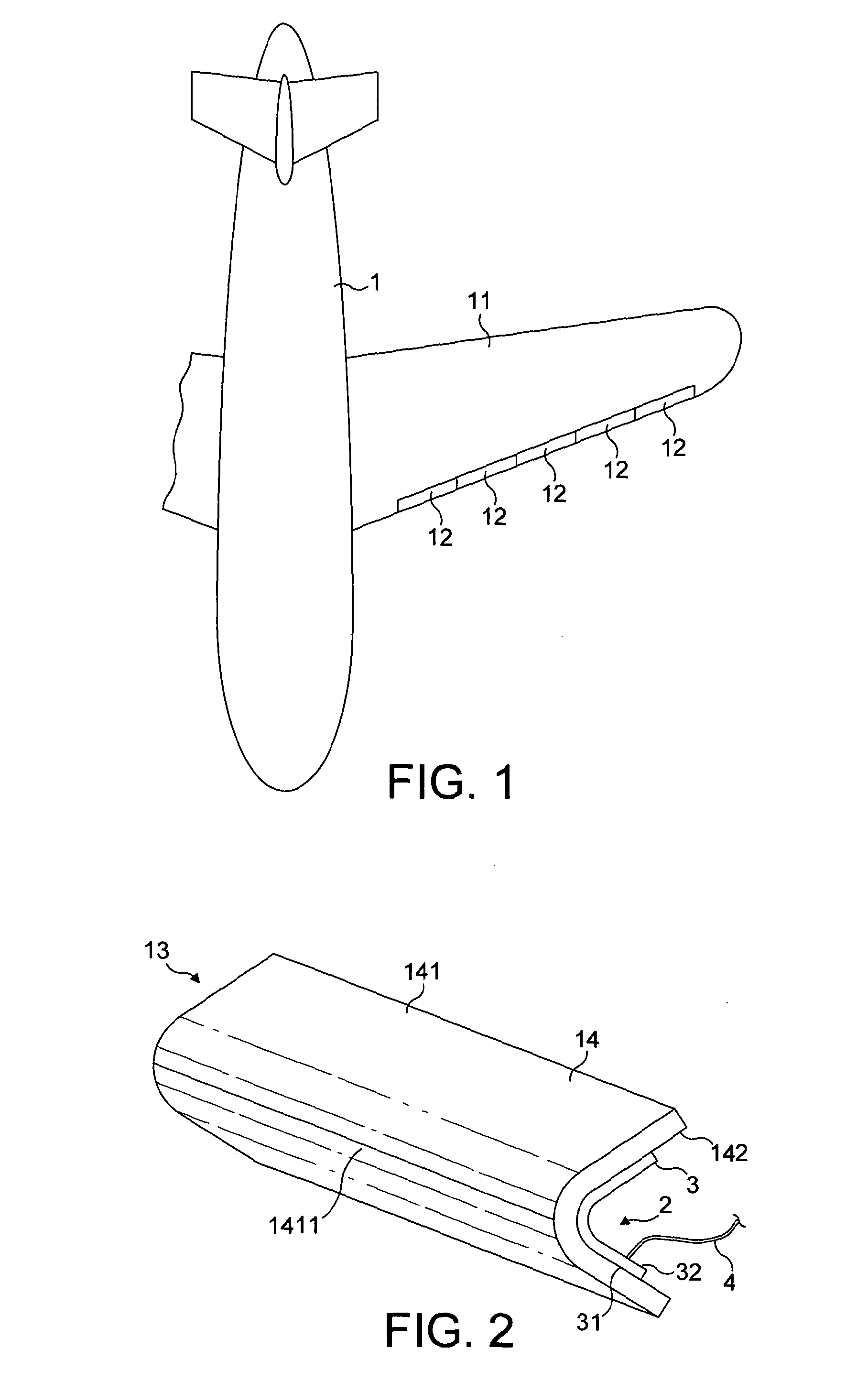
[0077]FIG. 1 is a plan view of an aircraft 1 having a wing 11 along the leading (forward) edge of which are positioned five wing slats 12. Each wing slat 12 incorporates an electrothermal ice protection system.

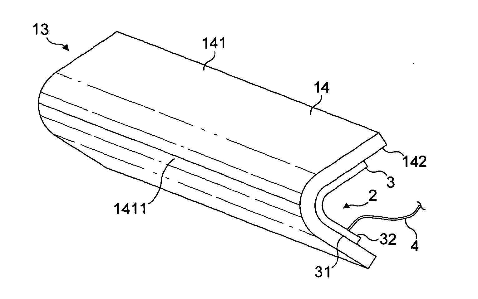
[0078]FIG. 2 is a diagrammatic perspective view of a demountable nose skin 13 of one of the wing slats 12 of FIG. 1. The configuration of the nose skin 13 may be generally the same as in EP-A-1,757,519 (GKN Aerospace) which discloses a wing slat having a demountable forward section comprising a nose skin.

[0079]The nose skin 13 comprises an erosion shield 14 and an electrically-powered heater 2.

[0080]The heater 2 comprises a heater blanket or mat 3 and a bundle of connectors 4 which connect the heater mat 3 to the power supply and control electronics of the aircraft 1.

[0081]The erosion shield 14 is generally rectangular and has a front surface 141 which is convexly curved and a rear surface 142 which is concavely curved. An apex 1411 of the front surface 141 provides the leadin...


PUM

PropertyMeasurementUnit
Fractionaaaaaaaaaa
Dielectric polarization enthalpyaaaaaaaaaa
Electrical conductoraaaaaaaaaa

Abstract

Electrical apparatus such as a heater (2) for an ice protection system for an aircraft (1) comprises a laminate such as a heater mat (3) and a connector (41-49). The laminate (3) comprises dielectric layers (50-58) and an electrical element such as a heater element (501), and each dielectric layer of the laminate comprises thermoplastic material. The connector (41-49) comprises a ribbon having first and second ends and a metal conductor (413, 423, 433). The ribbon comprises thermoplastic material and its first end (415, 425, 435, 445, 455, 465, 475, 485) is embedded in the laminate and is laminated to adjacent first and second ones of the dielectric layers (50-58) of the laminate. Because the thermoplastic material of the ribbon is the same as or is compatible with the thermoplastic material of the first and second dielectric layers, the formation of an undesirable discontinuity at the interfaces between the first end of the ribbon and the first and second dielectric layers is prevented. Thus, cracks are less likely to be initiated at the interfaces during the use of the electrical apparatus, and de-lamination is less likely to occur.

Description

FIELD OF THE INVENTION[0001]The present invention relates to electrical apparatus such as an electrothermal heater for an electrothermal ice protection system suitable for use in an aircraft or other aerodynamic structure such as a blade of a wind turbine to prevent ice from forming and / or to remove ice that has already formed. These two functions may be termed anti-icing and de-icing, respectively.BACKGROUND OF THE INVENTION[0002]For an aircraft, the in-flight formation of ice on the external surface of the aircraft is undesirable. The ice destroys the smooth flow of air over the aircraft surface, increases drag and decreases the ability of an aerofoil to perform its intended function.[0003]Also, built-up ice may impede the movement of a movable control surface such as a wing slat or flap. Ice which has built up on an engine air inlet may be suddenly shed in large chunks which are ingested into the engine and cause damage.[0004]It is therefore common for aircraft, and particularly ...

Claims


Application Information

Patent Timeline
IPC IPC(8): H05B3/02H05K13/00
CPCB64D15/12B64D2700/62078H05B3/36H05B2203/013Y10T29/49083H05B2203/033H05B2214/02H05B2203/016H05B3/18H05B2203/017H01R13/40
Inventor LEWIS, STUART MARTINENGLISH, PETER
Owner GKN AEROSPACE SERVICES LTD
Learn More