

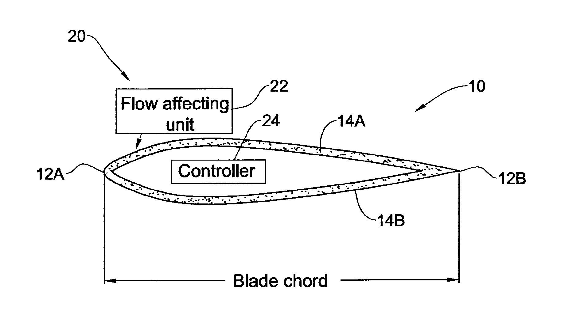
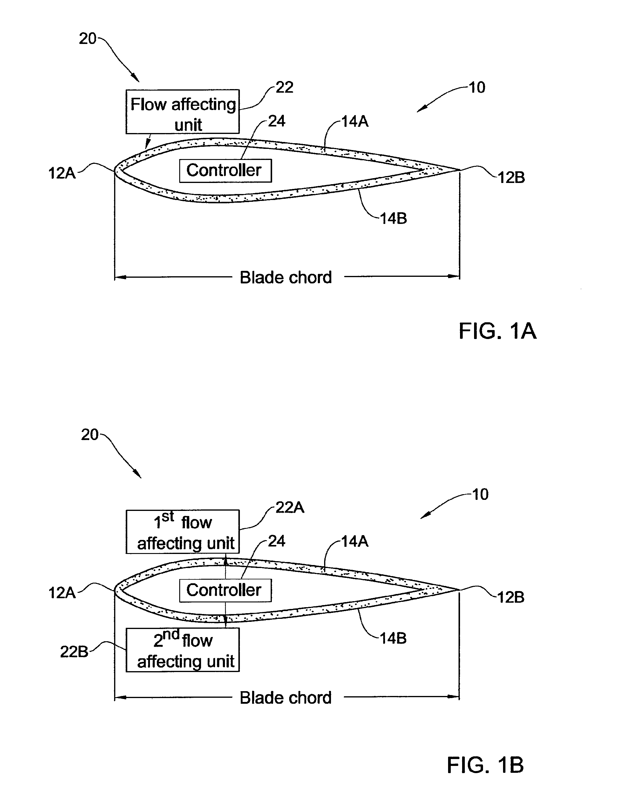
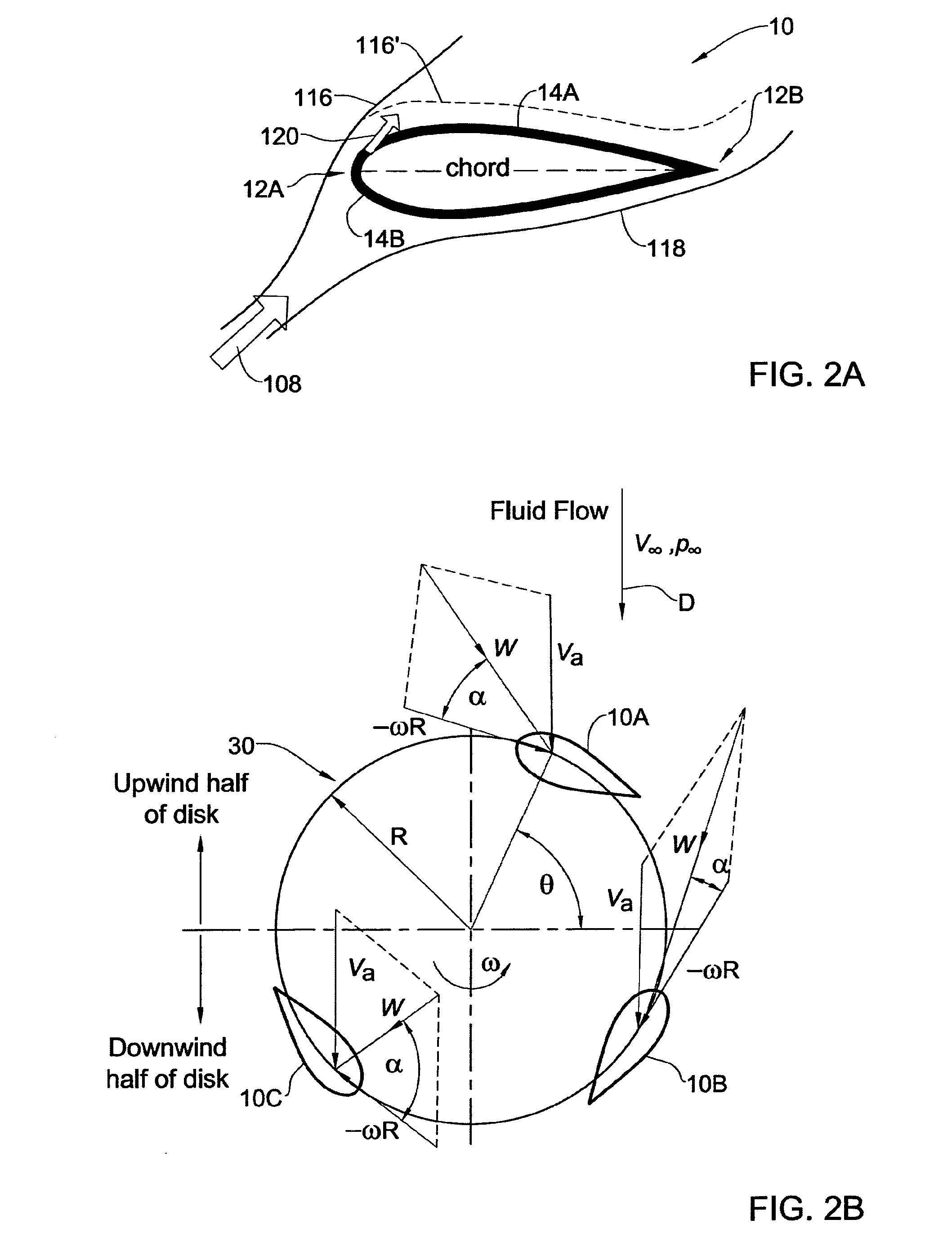
Flow control on a vertical axis wind turbine (VAWT)
a technology of wind turbine and vertical axis, which is applied in the direction of propellers, motors, transmission, etc., can solve the problems of reducing output power and stall conditions
- Summary
- Abstract
- Description
- Claims
- Application Information
AI Technical Summary
Benefits of technology
Problems solved by technology
Method used
Image

Examples
examples
[0100]Reference is now made to the following examples, which together with the above descriptions illustrate some embodiments of the invention in a non limiting fashion. The following are some computations based on experimental data carried out by the inventors to compare power generated by a blade in a VAWT of the present invention with a power generated by a typical VAWT blade which does not impart any momentum to air flowing thereon.
[0101]Experiments were performed of a NACA0012 airfoil with an 9-inch chord (c) and 24-inch span (203 mm×610 mm) that was equipped with fifty surface pressure ports and a two-dimensional leading edge active flow control slot of width hs=0.6 mm. Sections of the airfoil's ribbing were removed to render an essentially hollow interior which served as a plenum chamber. A roughness strip (Grit #100), used to trip the boundary layer, was fixed to the leading edge and extended to 4% chord on both top and bottom surfaces. Surface pressure data was augmented by...
PUM
 Abstract
Description
Claims
Application Information