

Smart window
a smart window and window technology, applied in the field of smart windows, can solve the problems of complex wiring and control circuits of electrically controllable devices, fixed performance cannot adapt to changing conditions,
- Summary
- Abstract
- Description
- Claims
- Application Information
AI Technical Summary
Benefits of technology
Problems solved by technology
Method used
Image

Examples
embodiment 1
[0077]An embodiment of this invention uses core-shell particles made using pre-synthesised 50 nm SiO2 particles dispersed in a 0.5 mol / l solution of vanadium isopropoxide in 2-propanol and 2-methoxyethanol. Acetic acid is used as chelating agent. Hydrolysis is performed at a water / V molar ratio of 2:1. The resulting particles are dried at in air at 200° C., and then annealed at 600° C. for 1 hour in a nitrogen atmosphere. This process produces particles with a core diameter ˜50 nm and shell thickness ˜7 nm. According to this invention the SPR occurs at a wavelength of ˜2200 nm. Thicker shells are produced using higher isopropoxide solutions.
embodiment 2
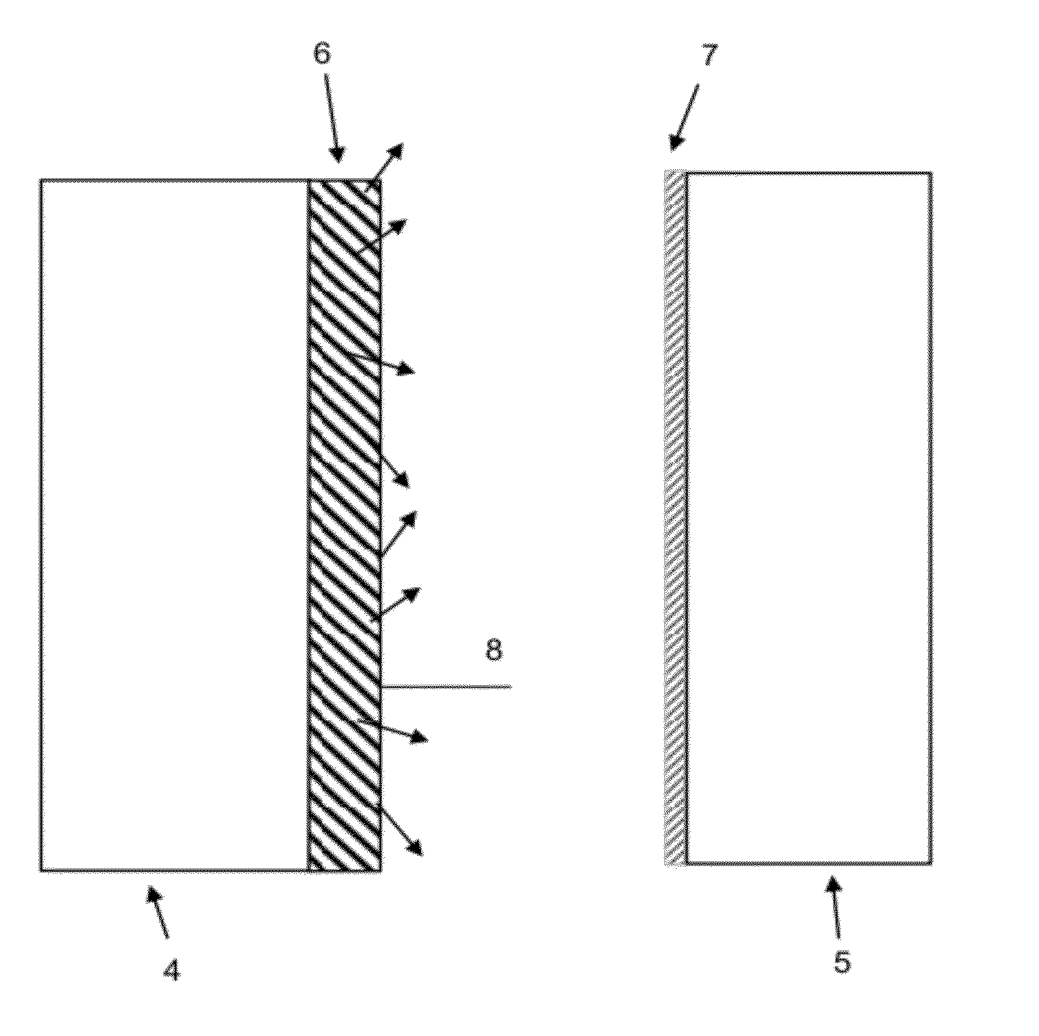
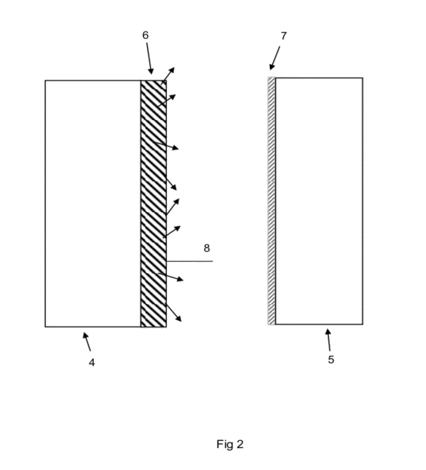
[0078]This embodiment of the invention uses the particles of Embodiment 1 dispersed in a transparent polymer host, such as Bayers two-pack polyurethane Desmophen 850 by gentle agitation and draw-coated onto a glass substrate or other transparent substrate. The binder is allowed to dry to produce a Smart Window film. The glass substrate is mounted in a frame, with the VO2 layer innermost, and then an additional pane of glass or other transparent substrate is mounted in the frame with a transparent indium-doped tin oxide layer innermost—facing the VO2 layer. In this way a complete smart window is formed.
embodiment 3
[0079]A thin film of VO2 doped as described above is deposited onto pre-structured glass or other transparent substrate via a suitable deposition technique such as PECVD. The glass or other substrate is pre-structured such that it contains surface roughness with feature size in the range 1 nm-200 nm. This pre-structuring can be achieved by a suitable lithography process such as electron beam lithography, UV interference lithography or block copolymer lithography. It could also use other nanoimprint lithography techniques. The optical properties of the final glass substrate are determined by the shape and size of the obtained features, and the thickness of the deposited VO2. A double glazing unit is constructed using an additional piece of ITO coated glass—the VO2 layer is on the internal face of the external pane of glass, the ITO layer is located on the internal surface of the internal pane of glass.
[0080]The present invention has been described herein in terms of the VO2 containin...
PUM
| Property | Measurement | Unit |
|---|---|---|
| size | aaaaa | aaaaa |
| diameter | aaaaa | aaaaa |
| particle size | aaaaa | aaaaa |
Abstract
Description
Claims
Application Information