Optical film and process for producing the same

a technology of optical film and slits, applied in the field of optical film, can solve the problems of easy cracking of anti-glare sheets, so as to improve abrasion resistance and mechanical properties, improve the effect of anti-glare or anti-newton rings, and moderate flexibility

Inactive Publication Date: 2012-11-29
DAICEL CHEM IND LTD
View PDF3 Cites 34 Cited by
  • Summary
  • Abstract
  • Description
  • Claims
  • Application Information

AI Technical Summary

Benefits of technology

[0018]According to the present invention, since a hardcoat layer which comprises a curable resin composition containing a thermoplastic resin and a nanometer-sized metal oxide fine particle is formed on at least one side of a transparent film, the metal oxide fine particle provides a nucleus for an uneven structure, and the resulting optical film has an improved anti-glareness or anti-Newton-ring property as well as improved abrasion resistance and mechanical properties. Moreover, due to the metal oxide fine particle, an optical film having an antistatic property can be obtained without requiring an antistatic treatment or an antistatic layer. Further, since the optical film contains the thermoplastic resin in addition to a cured resin, the film has a moderate flexibility and an improved hitting durability in a touch panel or the like. Furthermore, since the metal oxide fine particle can form an uneven structure, which expresses excellent optical characteristics, without addition of a flocculating agent due to easy aggregation of the metal oxide fine particle compared with aggregation of silica, an optical film from which a flocculating agent or the like is inhibited from bleeding out can be obtained.

Problems solved by technology

The anti-glare sheet, however, cannot relax a stress applied from outside, because the hardcoat layer is formed from only a curable resin.
Thus the anti-glare sheet easily cracks, and just a slight bending of the sheet causes slits running along the bending line.
In particular, when the sheet is used for an application undergoing repeated hitting (such as an upper transparent electrode of the touch panel), the sheet is insufficient in durability.
Moreover, since the anti-glare sheet has insufficient optical characteristics and a low anti-glareness, not only sparkling is observed but also a transmitted image is displayed unclearly.
Further, a flocculating agent necessary for the aggregation of a large amount of the silica fine particle causes bleeding out.
Furthermore, since the silica fine particle has an insufficient antistatic property, in Examples an antistatic layer containing an ITO fine particle is formed in addition to the hardcoat layer.

Method used


Image

  • Optical film and process for producing the same

Examples


example 1

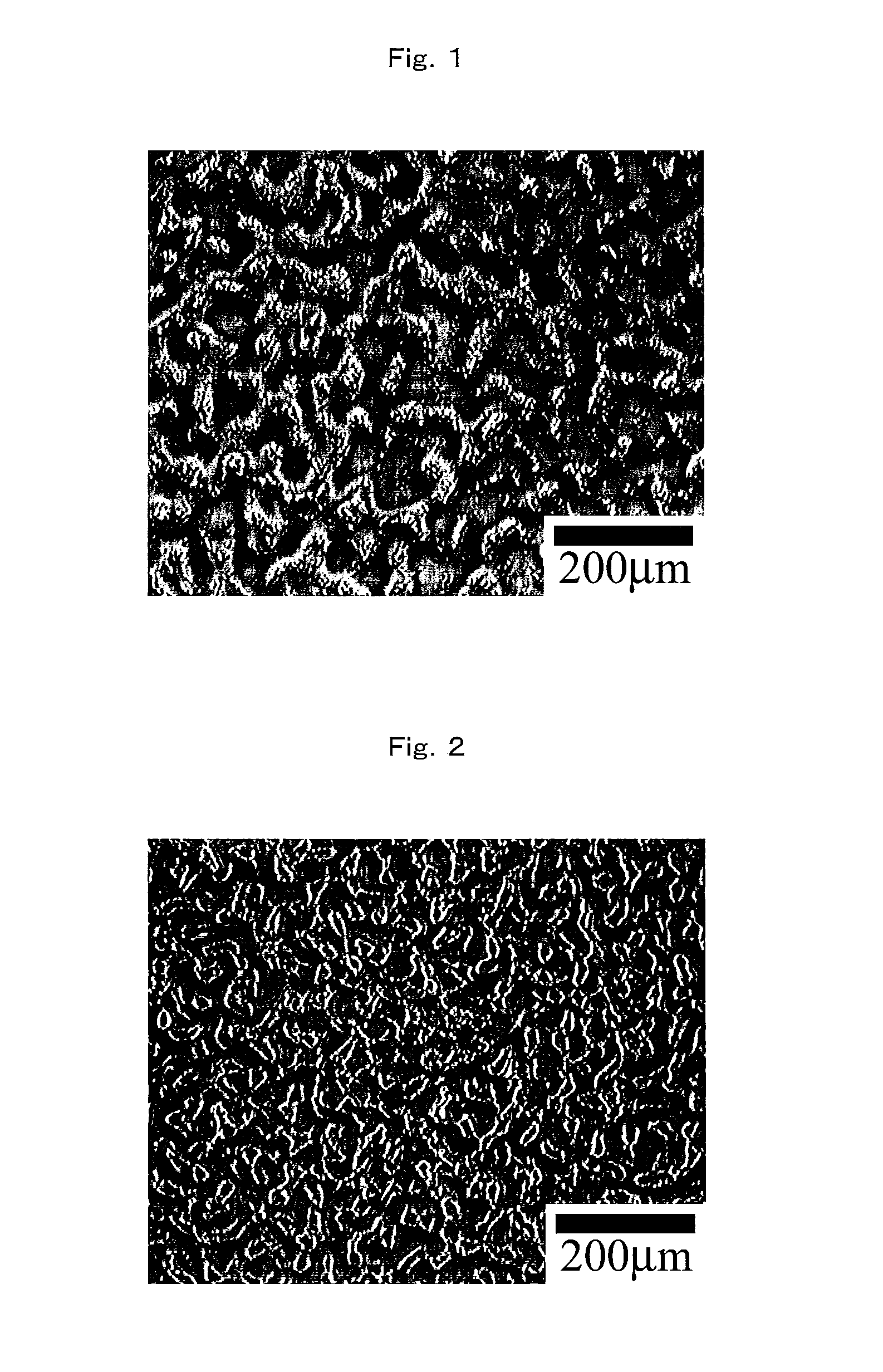
[0167]As a transparent film, a cellulose triacetate film (manufactured by Fujifilm Corporation, TAC, thickness: 80 μm) was used. The coating composition HC-1 for hardcoat layer was applied on the film with the use of a bar coater #30 and then dried at 70° C. for one minute. The coated film passed through an ultraviolet irradiation equipment (manufactured by Ushio Inc., a high-pressure mercury lamp, dose of ultraviolet ray; 800 mJ / cm2) for ultraviolet curing treatment to form a hardcoat layer having a hardcoat property and an uneven surface structure. The thickness of the hardcoat layer in the resulting optical film was about 10 μm. The observation of the surface of the resulting optical film by a laser-microscopic photograph is shown in FIG. 1.

example 2

[0168]An optical film was produced in the same manner as in Example 1 except that the coating composition HC-2 for hardcoat layer was used instead of the coating composition HC-1 for hardcoat layer.

example 3

[0169]An optical film was produced in the same manner as in Example 1 except that the coating composition HC-3 for hardcoat layer was used instead of the coating composition HC-1 for hardcoat layer.


PUM

PropertyMeasurementUnit
average primary particle sizeaaaaaaaaaa
Raaaaaaaaaaa
Raaaaaaaaaaa

Abstract

A hardcoat layer is a cured layer comprising a curable resin-precursor, a thermoplastic resin, and a fine particle having an average primary particle size of 1 to 100 nm, and the hardcoat layer is formed on at least one side of a transparent film. The thermoplastic resin may be a thermoplastic resin (particularly, a cellulose derivative) nonreactive to the curable resin-precursor. The ratio of the metal oxide fine particle is about 0.5 to 4 parts by weight relative to 100 parts by weight of the curable resin-precursor. The metal oxide fine particle may comprise at least one fine particle selected from the group consisting of antimony tin oxide, tin oxide, and zinc oxide. The curable resin-precursor may comprise a tetra- or more-functional precursor. The optical film of the present invention has excellent anti-glareness or anti-Newton-ring property and also has excellent abrasion resistance and mechanical properties.

Description

TECHNICAL FIELD[0001]The present invention relates to an optical film used in a display for a display screen of an electrical or electronic apparatus or a precision instrument, and a process for producing the same.BACKGROUND ART[0002]In recent years, remarkable progress as a display apparatus has been made in liquid crystal displays (LCD) for television (TV) application or movie display application, and the liquid crystal display has become rapidly popular. For example, the development of a liquid crystal material having a high-speed responsiveness or the improvement of a drive system such as overdrive has overcome weak points (poor movie display) of a conventional liquid crystal, and the production engineering innovation supporting the increase in display size of the display has progressed.[0003]The display surfaces of these displays are usually subjected to a surface treatment for inhibiting reflection of an ambient light (sun light or light from a light source around the display)...

Claims


Application Information

Patent Timeline
Patent Type & Authority Applications(United States)
IPC IPC(8): C08F2/48B32B5/16
CPCG02B1/105Y10T428/25Y10T428/24413Y10T428/256G02B1/16G02B1/14B32B5/16B32B7/02B32B27/18B32B27/26C08F2/48G02B1/00G02B1/10G02F1/1335G02F1/133502
Inventor USHIDA, HIROAKIHAYASHI, MASAKI
Owner DAICEL CHEM IND LTD
Why Eureka
Try Eureka