
Photoacoustic imaging apparatus and photoacoustic imaging method

Inactive Publication Date: 2012-11-29
CANON KK
View PDF9 Cites 24 Cited by
  • Summary
  • Abstract
  • Description
  • Claims
  • Application Information

AI Technical Summary

Benefits of technology

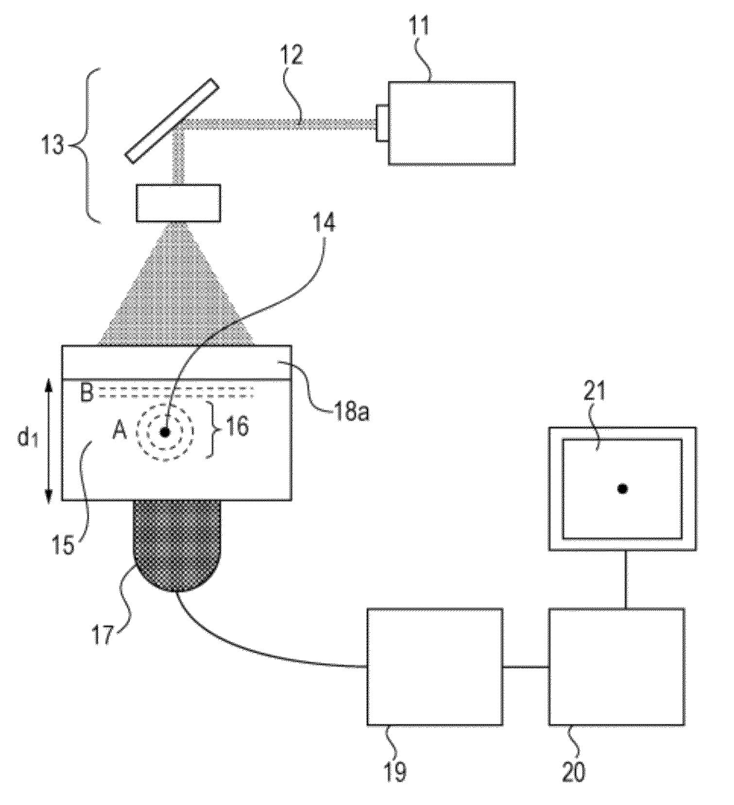
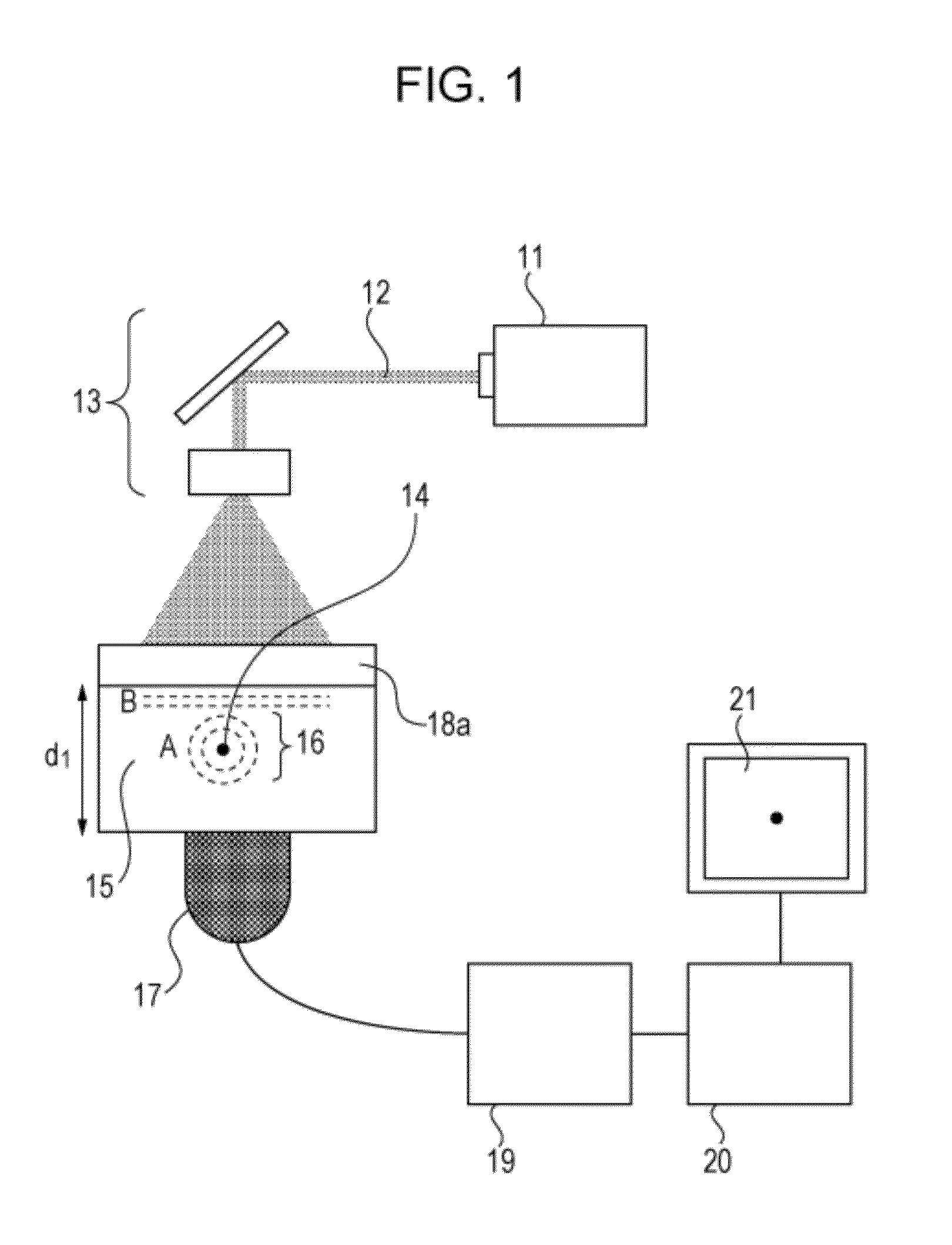
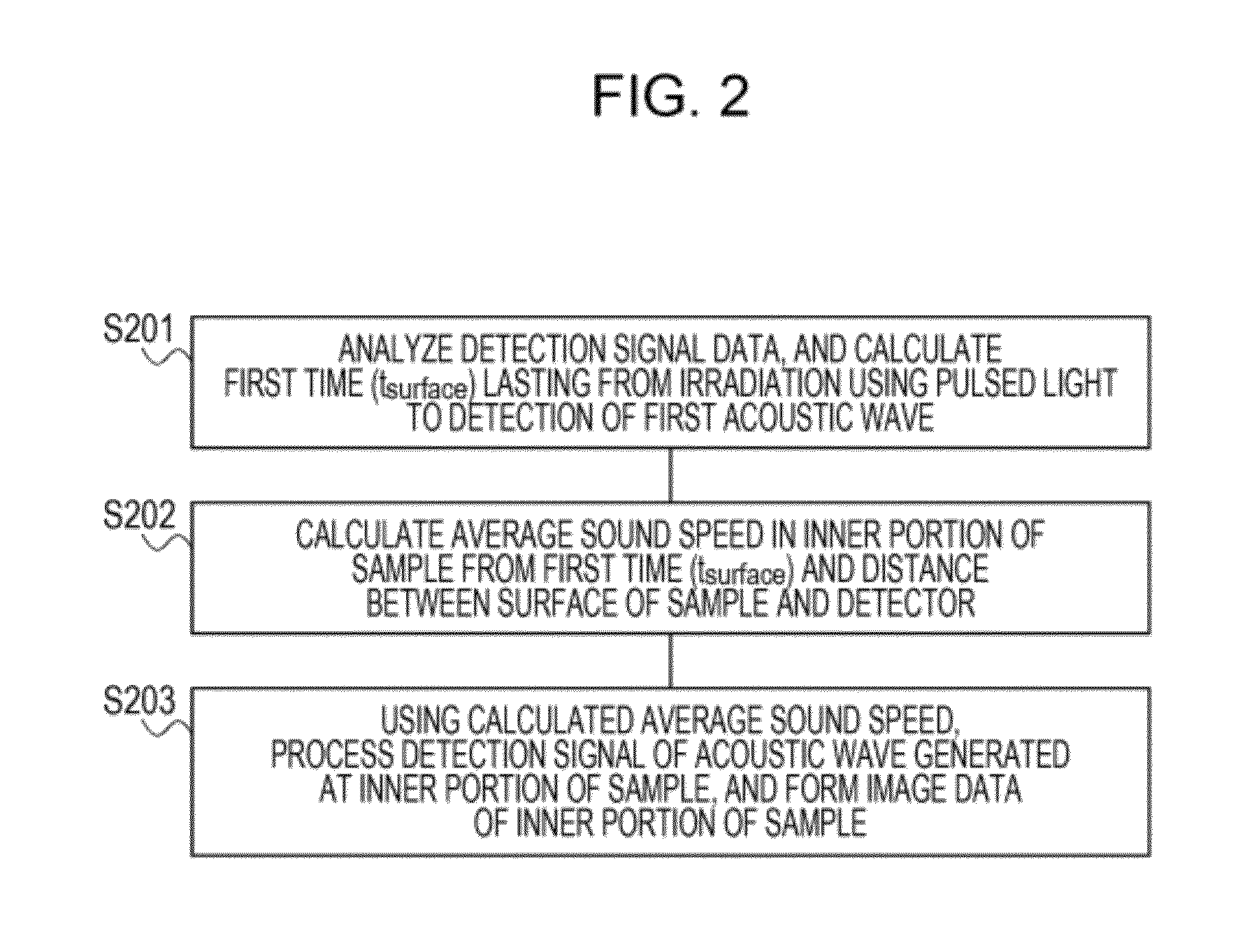
[0010]The present invention can provide a photoacoustic imaging apparatus that can easily measure an average sound speed in an inner portion of a sample by receiving a photoacoustic wave that is generated at a surface of the sample and that propagates through the inner portion of the sample. This makes it possible to obtain high-resolution image data using an actually measured average sound speed.

Problems solved by technology

Therefore, a long measurement time is required until image data is formed.

Method used


Image

  • Photoacoustic imaging apparatus and photoacoustic imaging method
  • Photoacoustic imaging apparatus and photoacoustic imaging method
  • Photoacoustic imaging apparatus and photoacoustic imaging method

Examples


example 1

[0050]An exemplary imaging apparatus using photoacoustic tomography to which the embodiment is applied will be described using the schematic view of the apparatus shown in FIG. 1. In the example, as a light source 11, a Q switch YAG laser generating pulsed light of approximately 10 nanoseconds at a wavelength of 1064 nm was used. Energy of a light pulse emitted from pulsed laser light 12 was 0.6 J. Using an optical system 13, such as a mirror and a beam expander, the pulsed light was expanded to a radius of approximately 2 cm. A phantom or a simulation of a living body was used as a sample 15. For the phantom, 1% Intralipid with gelatin was used. The average sound speed in the phantom was a known value of 1512 m / sec. The size of the phantom was such that its width was 12 cm, its height was 8 cm, and its depth was 4 cm. As an optical absorber 14, a black rubber wire having a diameter of 0.03 cm was buried near the center in the phantom. As a result of interposing the phantom between ...

second embodiment

[0058]In the first embodiment, the average sound speed is calculated by using only the acoustic wave (first acoustic wave) generated from one location. In a second embodiment, the average sound speed is calculated by using acoustic waves generated at a plurality of surfaces of a sample. That is, the average sound speed is calculated from detection signals obtained from a first acoustic wave and a second acoustic wave generated at a surface of the sample that differs from the surface of the sample where the first acoustic wave is generated. This will hereunder be described on the basis of Example 2.

example 2

[0059]Example 2 in which, in an imaging apparatus using photoacoustic tomography, laser was used for irradiation from two directions will be described with reference to FIG. 5A. The basic structure of the imaging apparatus according to Example 2 was the same as that of the imaging apparatus according to Example 1 except that a sample 15 was interposed between two plates 18a and 18b, to regulate the size of the sample. That is, the size of the sample was regulated by controlling the interval between the plates. The thickness of each plate was 1 cm. The sample could be irradiated through the plate 18b from a side of a probe 17 and in a direction that is the same as that in Example 1. A phantom used was one having titanium oxide and ink mixed with urethane rubber. The size of the phantom was such that its width was 8 cm, its height was 8 cm, and its depth was 5 cm. An optical absorber having a columnar shape that was 0.5 cm in diameter and having a high absorption coefficient with resp...


PUM


Abstract

A photoacoustic imaging apparatus includes a detector that outputs detection signals by detecting acoustic waves generated at surfaces and an inner portion of a sample by irradiating the sample with light; and a signal processing unit that generates image data using the detection signal. The signal processing unit calculates an average sound speed in the inner portion of the sample by using the detection signal of the acoustic wave generated at the surface of the sample and propagated through the inner portion of the sample, and generates the image data using the average sound speed and the detection signal of the acoustic wave generated at the inner portion of the sample.

Description

TECHNICAL FIELD[0001]The present invention relates to a photoacoustic imaging apparatus and a photoacoustic imaging method in which an acoustic wave that is generated from an inner portion of a sample by irradiating the sample with light is detected, and a detection signal thereof is processed to obtain image data of the inner portion of the sample.BACKGROUND ART[0002]In the medical field, research in optical imaging apparatuses that irradiate a living body with light from a light source, such as a laser, and that performs imaging on information of an inner portion of the living body obtained on the basis of incident light is being positively conducted. Photoacoustic tomography (PAT) is one example of optical imaging technology. In the photoacoustic tomography, a living body is irradiated with pulsed light generated from a light source, and an acoustic wave (typically, an ultrasonic wave) generated from living tissues that have absorbed energy of the pulsed light propagated through / ...

Claims


Application Information

Patent Timeline
IPC IPC(8): A61B6/00
CPCA61B5/0095G01N29/2418G01N21/1702A61B8/0825
Inventor FUKUTANI, KAZUHIKOASAO, YASUFUMI
Owner CANON KK
Learn More