Silicon wafer and method of manufacturing thereof, and method of manufacturing semiconductor device

a technology of silicon wafers and semiconductor devices, applied in the field of silicon wafers, can solve the problems of increasing sub-threshold current, strong thermal stress inside the wafer, and the channel length of mos transistors, so as to prevent the occurrence of dislocation and prevent the effect of dislocation

Active Publication Date: 2012-12-06
SUMCO CORP
View PDF6 Cites 16 Cited by
  • Summary
  • Abstract
  • Description
  • Claims
  • Application Information

AI Technical Summary

Benefits of technology

[0036]As described above, according to one aspect of the present invention, it is possible to provide an epitaxial wafer having a wafer doped with high concentrations of nitrogen or boron, as well as a silicon wafer on which dislocation is preventable even when the LSA treatment is performed in the device processes.
[0037]According to one aspect of the present invention, it is possible to provide a manufacturing method of an epitaxial wafer having a wafer doped with high concentrations of nitrogen or boron, as well as a manufacturing method of a silicon wafer on which dislocation is preventable even when the LSA treatment is performed in the device processes.
[0038]Furthermore, according to one aspect of the present invention, it is possible to provide a manufacturing method of a semiconductor device using an epitaxial wafer doped with high concentrations of nitrogen or boron, as well as a manufacturing method of a semiconductor device on which the LSA treatment does not trigger dislocation.
[0039]According to another aspect of the present invention, the LSA treatment is performed under a predetermined condition. Therefore, it is possible to prevent the dislocation, which is triggered by plate-like oxygen precipitates, from generating.
[0040]According to still another aspect of the present invention, even when plate-like oxygen precipitates grow before the LSA treatment, it is possible to prevent the occurrence of dislocation caused by the LSA treatment.

Problems solved by technology

However, in recent years, a channel length of a MOS transistor has been so designed as to be very short.
The problem thereof is an increase in sub-threshold current due to a short channel effect.
However, in the LSA treatment, a steep temperature gradient is formed not only in the thickness direction of the wafer but also in the in-plane direction, causing strong thermal stress inside the wafer.
As a result, in a photolithography process, a so-called overlay error occurs.

Method used


Image

  • Silicon wafer and method of manufacturing thereof, and method of manufacturing semiconductor device
  • Silicon wafer and method of manufacturing thereof, and method of manufacturing semiconductor device
  • Silicon wafer and method of manufacturing thereof, and method of manufacturing semiconductor device

Examples


example 1

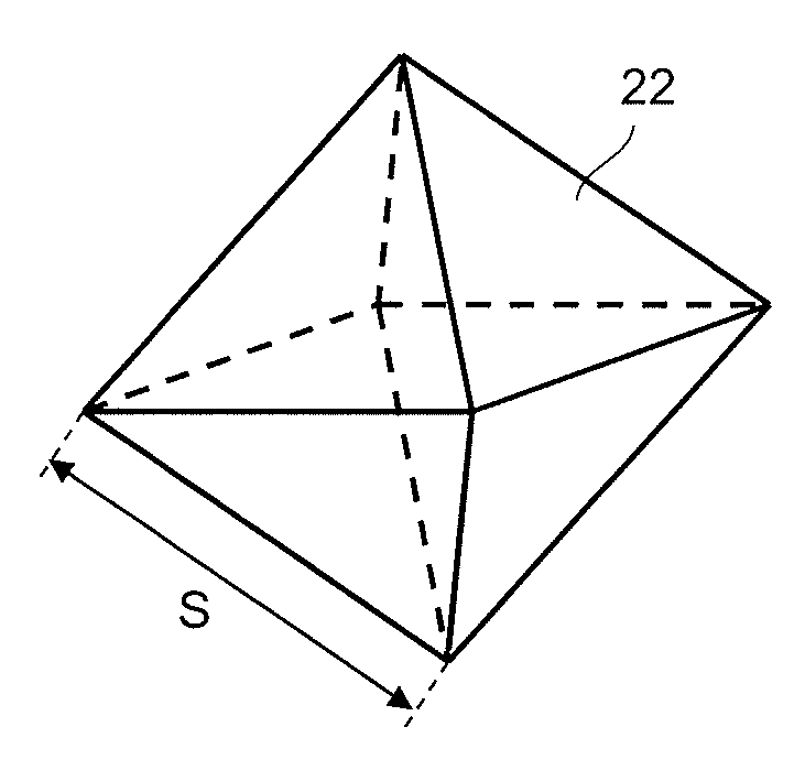
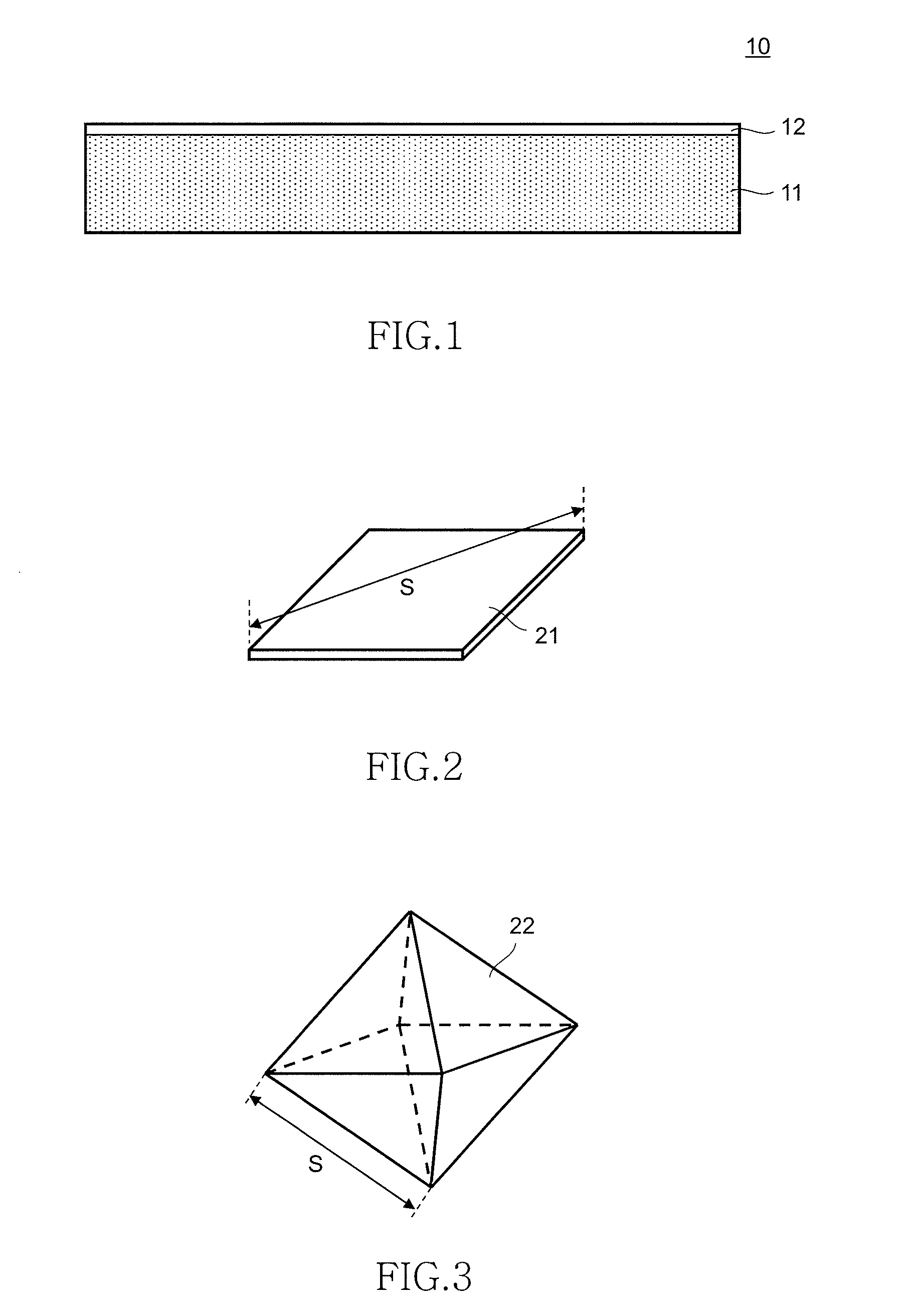
[0070]A plurality of polished wafers with an interstitial oxygen concentration of 12.5×10¹⁷ atoms / cm3 and a diameter of 300 mm were prepared. The wafers were subjected to various kinds of thermal treatments, and oxygen precipitates of different sizes and shapes were formed. The sizes and shapes of the precipitates were identified as different samples to which the same kinds of thermal treatment were applied were measured and observed under a transmission electron microscope (TEM). Table 1 shows the sizes and shapes of the precipitates that exist in a region extending to a depth of 50 μm or less from the outer layer of the wafer.

[0071]Then, the LSA treatment was applied to each wafer on which precipitates were formed. The maximum temperature on the wafer surface of each sample is shown in Table 1. After the LSA treatment, an X-ray topography device was used to confirm whether or not dislocation had occurred.

[0072]As a result, as shown in Table 1, in Samples 1 to 24 whose oxygen preci...

example 2

[0074]The following wafers were prepared: a 300 mm epitaxial wafer in which an epitaxial layer was formed on a wafer doped with nitrogen, and a 300 mm epitaxial wafer in which an epitaxial layer was formed on a wafer doped with boron. The doping amounts are shown in Table 2. The interstitial oxygen concentration of the wafer of each sample was 11.5×10¹⁷ to 13.6×10¹⁷ atoms / cm3.

[0075]The epitaxial wafers were inserted into a vertical furnace kept at 700° C. After the temperature was increased to a predetermined temperature at a predetermined rate, the temperature was kept for a predetermined period of time. For each sample, the temperature-rising rate, retention temperature, and retention time are shown in Table 2. After the thermal treatment, the temperature was lowered to 700° C. at a temperature-lowering rate of 3° C. per minute, and the wafers were taken out. In this manner, precipitate nuclei were formed on the wafer bodies. However, the above thermal treatment was omitted for Sa...

example 3

[0080]The following wafers were prepared: a 300 mm epitaxial wafer in which an epitaxial layer was formed on a wafer doped with nitrogen, and a 300 mm epitaxial wafer in which an epitaxial layer was formed on a wafer doped with boron. The doping amounts are shown in Table 3. The interstitial oxygen concentration of the wafer of each sample was 11.5×10¹⁷ to 13.6×10¹⁷ atoms / cm3.

[0081]The epitaxial wafers were inserted into a vertical furnace kept at 700° C. After the temperature was increased to a predetermined temperature at a rate of 5° C. per minute, the temperature was kept for 5 minutes. For each sample, the retention temperature is shown in Table 3. After the thermal treatment, the temperature was lowered to 700° C. at a temperature-lowering rate of 3° C. per minute, and the wafers were taken out. In this manner, precipitate nuclei were formed on the wafer bodies.

[0082]Then, the precipitate nuclei grew as thermal treatment was carried out on each sample at 850° C. for 30 minutes...


PUM

PropertyMeasurementUnit
temperatureaaaaaaaaaa
melting pointaaaaaaaaaa
temperatureaaaaaaaaaa

Abstract

An object of the present invention is to provide an epitaxial wafer on which dislocation is preventable even when a LSA treatment is performed in device processes. An epitaxial wafer according to the present invention includes a wafer 11 whose nitrogen concentration is 1×10¹² atoms/cm3 or more or whose specific resistance is 20 mΩ·cm or less by boron doping, and an epitaxial layer 12 provided on the wafer 11. On the wafer 11, if a thermal treatment is performed at 750° C. for 4 hours and then at 1,000° C. for 4 hours, polyhedron oxygen precipitates grow predominantly over plate-like oxygen precipitates. Therefore, in the device processes, plate-like oxygen precipitates cannot be easily formed. As a result, even when the LSA treatment is performed after various thermal histories in the device processes, it is possible to prevent the dislocation, which is triggered by oxygen precipitates, from generating.

Description

TECHNICAL FIELD[0001]The present invention relates to a silicon wafer and a manufacturing method thereof, and particularly to a silicon wafer that is used for device processes including a LSA (Laser Spike Anneal) treatment, and a manufacturing method thereof. Moreover, the present invention relates to a manufacturing method of a semiconductor device, and particularly to a manufacturing method of a semiconductor device including LSA treatment.DESCRIPTION OF RELATED ART[0002]In manufacturing processes (or so-called device processes) of a semiconductor device, various kinds of thermal treatments are performed on a silicon wafer. For example, in order to form a source / drain region of a MOS transistor, after the ion implantation of dopants into the silicon wafer is carried out, annealing is carried out to activate the dopants. As for the annealing for activating dopants, a method of heating the entire surface of the wafer with a lamp furnace or the like is generally used.[0003]However, i...

Claims


Application Information

Patent Timeline
Patent Type & Authority Applications(United States)
IPC IPC(8): H01L21/20H01L29/06
CPCH01L21/3225H01L21/268H01L21/265H01L21/324
Inventor ONO, TOSHIAKIFUJISE, JUN
Owner SUMCO CORP
Why Eureka
Try Eureka