Manufacturing Method for Color Filter Substrate, Photomask and Photoreactive Layer

a color filter substrate and manufacturing method technology, applied in the field of liquid crystal display, can solve the problems of degrading contrast ratio, affecting the quality of color filter substrates, so as to improve aperture ratio and contrast ratio, and simplify manufacturing process

Inactive Publication Date: 2012-12-06
TCL CHINA STAR OPTOELECTRONICS TECH CO LTD
View PDF2 Cites 17 Cited by
  • Summary
  • Abstract
  • Description
  • Claims
  • Application Information

AI Technical Summary

Benefits of technology

[0007]A primary objective of the present disclosure is to provide a manufacturing method for a color filter substrate, a photomask and a photoreactive layer, which allow for a simplified manufacturing process and can improve the aperture ratio and the contrast ratio.

Problems solved by technology

However, this process cannot separate the colors through a single exposure; instead, the sequence of coating, exposing and developing steps must be performed repeatedly in order to form resist layers of different colors.
Furthermore, because a number of layers have to be produced separately, a height difference is caused between areas where BM regions overlap with R / G / B regions and pixel active areas (also termed as AA areas hereinafter), which leads to different tilting angles of liquid crystal molecules; consequently, light leakage occurs and the contrast ratio is degraded.
Therefore, the manufacturing method for the color filter substrate in the prior art is complex and tends to cause degradation in the aperture ratio and the contrast ratio.

Method used


Image

  • Manufacturing Method for Color Filter Substrate, Photomask and Photoreactive Layer
  • Manufacturing Method for Color Filter Substrate, Photomask and Photoreactive Layer
  • Manufacturing Method for Color Filter Substrate, Photomask and Photoreactive Layer

Examples


Embodiment Construction

[0045]The present disclosure is more particularly described in the following examples that are intended as illustrative only since numerous modifications and variations therein will be apparent to those skilled in the art.

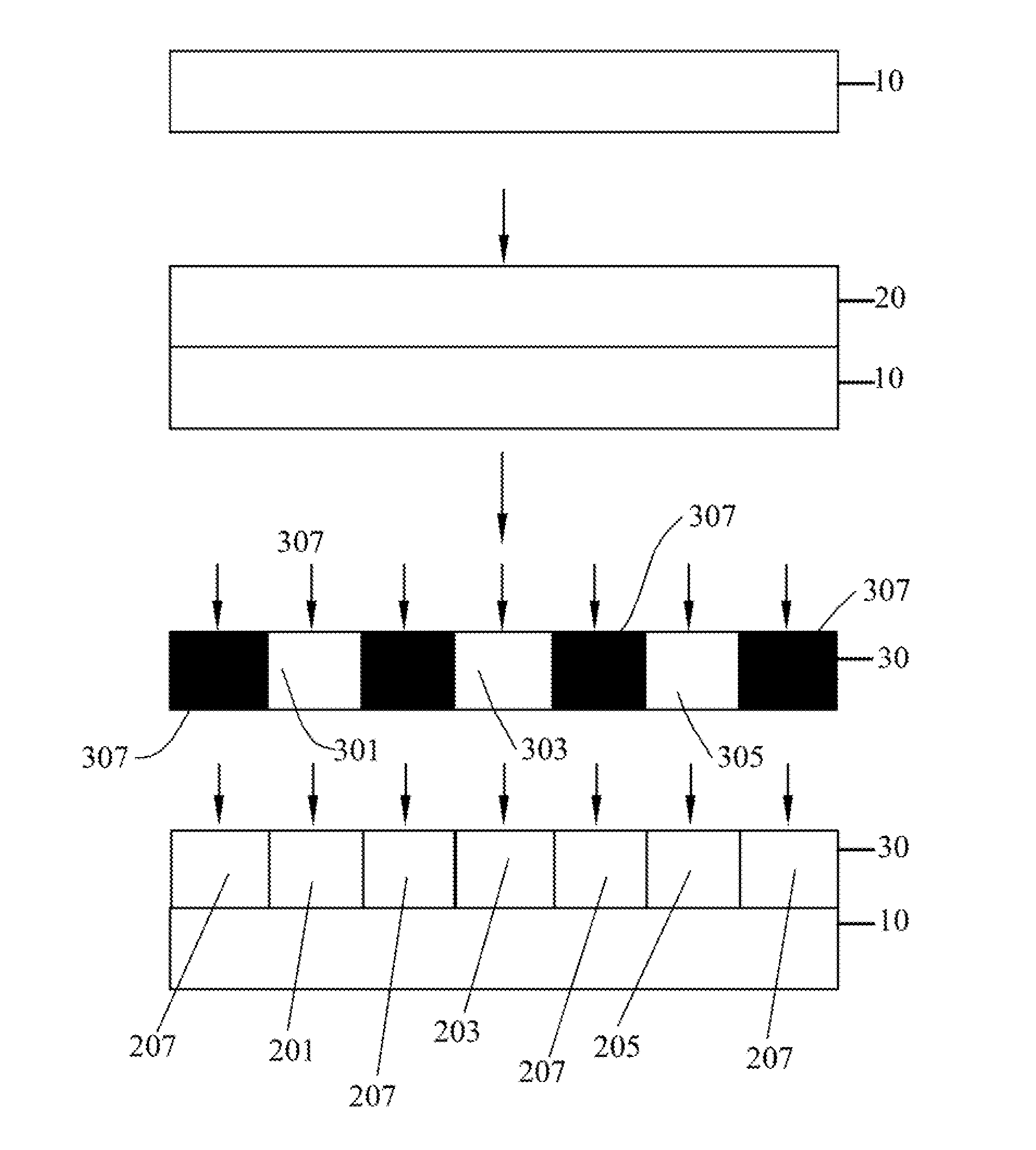
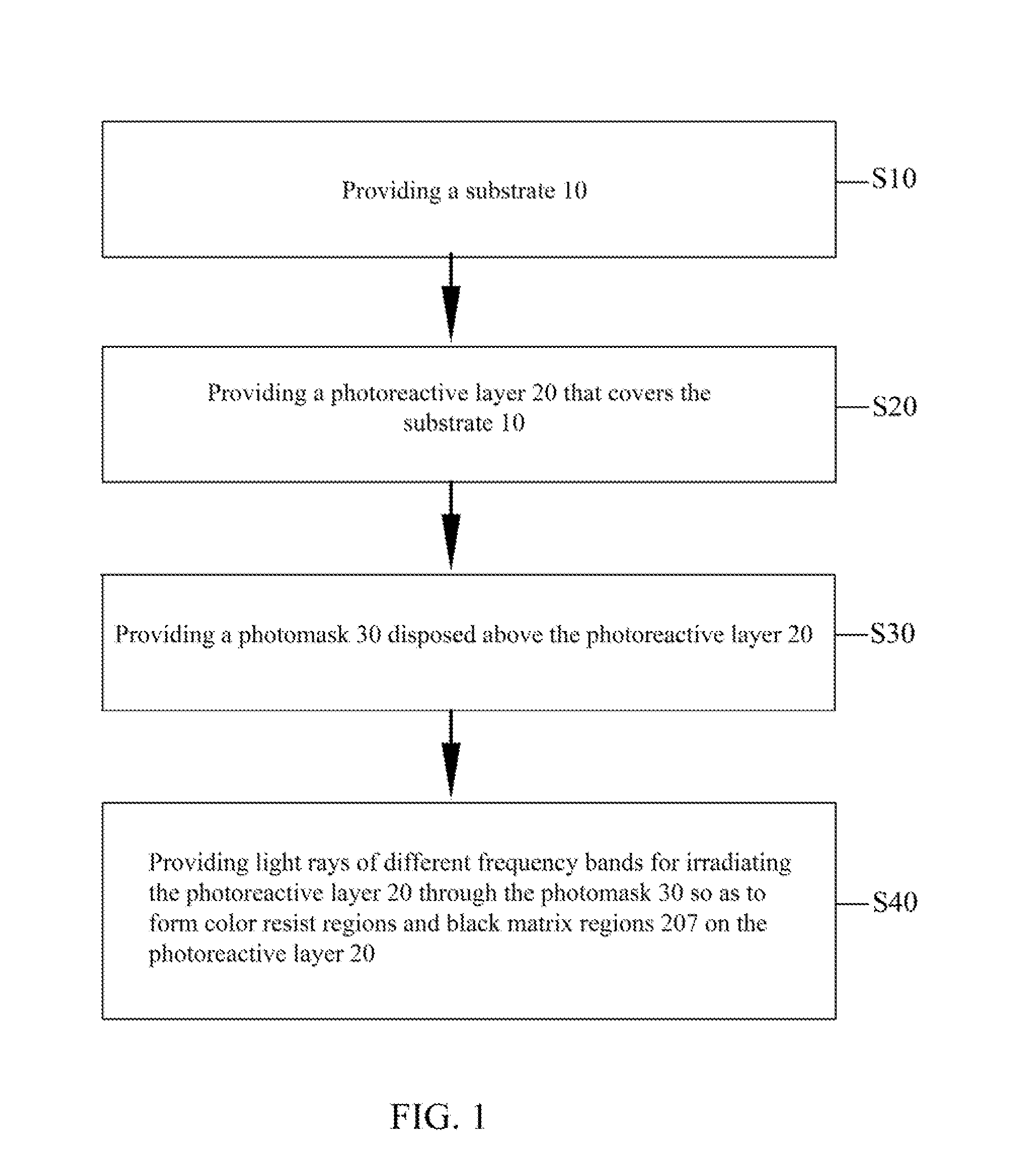
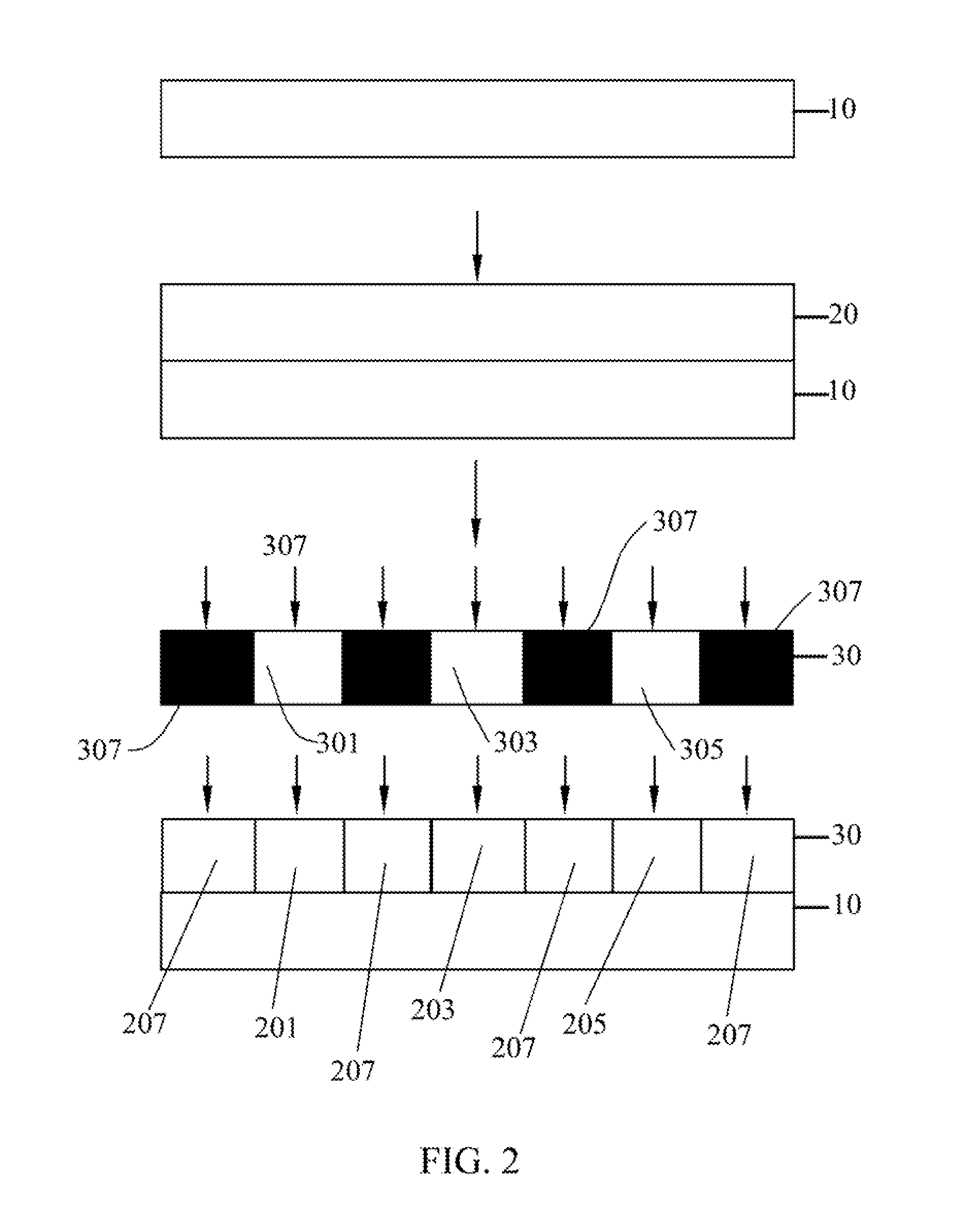
[0046]Referring to FIG. 1 and FIG. 2 together, FIG. 1 is a flowchart of a manufacturing method for a color filter substrate according to the present disclosure, and FIG. 2 is a view illustrating steps of the manufacturing method for the color filter substrate according to the present disclosure.

[0047]The present disclosure provides a manufacturing method for a color filter substrate, which comprises the following steps:

[0048]S10: providing a substrate 10.

[0049]In this step, generally a glass substrate is used for the substrate 10. The glass substrate is cleaned of organic or inorganic foreign matters thereon, and a surface thereof is kept flat.

[0050]S20: providing a photoreactive layer 20 covering the substrate 10.

[0051]In this step, the photoreactive layer 20 is d...


PUM

PropertyMeasurementUnit
frequencyaaaaaaaaaa
coloraaaaaaaaaa
frequency bandsaaaaaaaaaa

Abstract

A manufacturing method for a color filter substrate is disclosed in the present disclosure, which comprises the following steps of: providing a substrate; providing a photoreactive layer that covers the substrate; providing a photomask disposed above the photoreactive layer; and providing light rays of different frequency bands for irradiating the photoreactive layer through the photomask so as to form color resist regions and black matrix regions on the photoreactive layer respectively. A photomask and a photoreactive layer for preparing a color resist layer on a color filter substrate are also provided in the present disclosure. Thereby, the present disclosure can advantageously shorten the production cycle, and improve the aperture ratio and the contrast ratio.

Description

FIELD OF THE INVENTION[0001]The present disclosure generally relates to the technical field of liquid crystal displaying, and more particularly, to a manufacturing method for a color filter substrate, a photomask and a photoreactive layer.BACKGROUND OF THE INVENTION[0002]Owing to their advantages such as light weight, thin profile, small size, low power consumption, free of radiation and low manufacturing cost, liquid crystal displays (LCDs) have become a mainstream product in the flat panel display market. The LCDs are very suitable for use in desktop computers, palmtop computers, personal digital assistants (PDAs), mobile phones, TV sets, and various office automation apparatuses and audio & video (AV) apparatuses.[0003]Liquid crystal panels are known as key components of LCDs. Currently, a common liquid crystal panel is formed by a thin-film transistor (TFT) substrate and a color filter (CF) substrate laminated on each other with a liquid crystal layer being sandwiched therebetwe...

Claims


Application Information

Patent Timeline
Patent Type & Authority Applications(United States)
IPC IPC(8): G03F7/20G02B5/23G03F1/00
CPCG02B5/201G02F1/133516G02B5/22
Inventor CHEN, HSIAO HSIENLEE, KUAN-CHENG
Owner TCL CHINA STAR OPTOELECTRONICS TECH CO LTD
Why Eureka
Try Eureka