Coal decomposition equipment

a technology of coal decomposition equipment and equipment, which is applied in the direction of muffler furnaces, furnaces, lighting and heating apparatus, etc., can solve the problems of large processing capacity, increase the cost of raw materials, and lack of high heat value, so as to achieve high heat value, fully utilize energy, and be more fast and efficient

Inactive Publication Date: 2012-12-06
ZHU SHUCHENG +4
View PDF68 Cites 7 Cited by
  • Summary
  • Abstract
  • Description
  • Claims
  • Application Information

AI Technical Summary

Benefits of technology

[0006]To solve the above problems in prior arts, an object of the present invention is to provide a method and equipment for pulverized coal decomposition, which can decompose the pulverized coal directly and thus improving their overall utilization value and saving energy, and so as to enhance its economic and social benefits.
[0016]According to the present invention, an entirely new heating method is introduced into pulverized coal decomposition field, so a large amount of heat produced by the flame gas pipeline heating facility are conducted and radiated to the pulverized coal in the channel. Thus, the pulverized coal can fully absorb the heat so as to be heated for being decomposed to the gas, coal tar and coal with high heat-value in the channel. The gas and coal tar gas communicate with a gas dedust and liquefaction facility outside of the kiln body through the coal decomposition gas collecting pipe, and the decomposed gas and coal tar gas are collected, dedusted, separated, and pressure liquefied by the gas dedust and liquefaction facility. The flame gas radiating pipe consists of multiple parallel close-packed pipes or tube mesh close-packed pipes so that the produced heat can be transferred to the pulverized coal more sufficiently. The decomposition equipment for coal disclosed by the present invention makes the decomposition and separation of the pulverized coal more fast and efficient so as to save and fully utilize energy and greatly increase the utilization rate and level of coal resources, thus it will produce a significant economic and social benefits for the entire society.

Problems solved by technology

However, the above-mentioned technology is required to block pulverized coal or sift lamp coal, as a result, it increases the cost of raw material, or cause the produced gas without a high heat value, a big additional value, and a significant economy and social benefits.
The method has a large processing capacity because of its large temperature difference, small particles and fast heat transfer.
This results in a significant resources wasting and environmental pollution.
Because the coal lumps on the clapboard are accumulated to a certain thickness, so they cannot be uniformly heated and decomposed, and are required to be cyclically heated and decomposed by the decomposed gas.
More importantly, since the large amount of holes for ventilation and circulatory function provided on the clapboard, pulverized coal can leak from the holes.
Thus, it will increase the cost of pulverized coal decomposition, and reduce the economic benefits because the pulverized coal cannot be directly used for coal decomposition.

Method used


Image

  • Coal decomposition equipment
  • Coal decomposition equipment
  • Coal decomposition equipment

Examples


embodiment 1

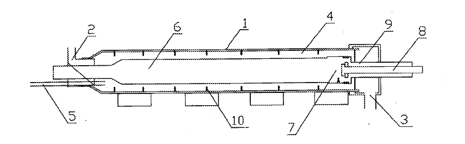
[0022]Referring to FIG. 1, a coal decomposition equipment comprises an airtight kiln body 1 with coal inlet 2 and coal outlet 3. The kiln body 1 is a horizontal and rotary kiln. A flame gas pipeline heating facility is set in the kiln body 1 and a channel 4 for impelling and decomposing coal is formed between the flame gas pipeline heating facility and an inner wall of the kiln body. A coal decomposition gas collecting pipe 5 is provided on the kiln body 1 to communicate with the channel 4, and an impelling board 10 is set in the inner wall of the kiln body 1. The flame gas pipeline heating facility includes a flame gas heat dissipation pipe 6 and a combustor chamber 7. The combustor chamber 7 communicates with a fuel supply pipe 8 and an air supply pipe 9 which are both set outside of the kiln body 1. The fuel in the fuel supply pipe 8 and the air in the air supply pipe 9 are mixed combustion in the combustor chamber 7, and the produced the high temperature flame gas come into the ...

embodiment 2

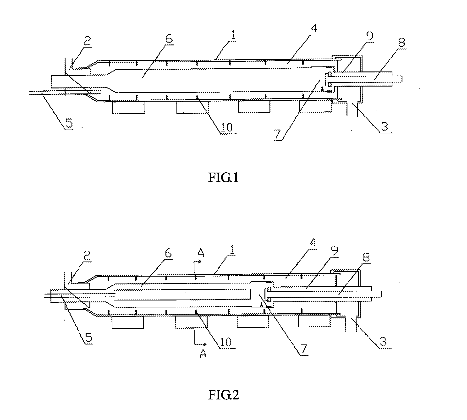
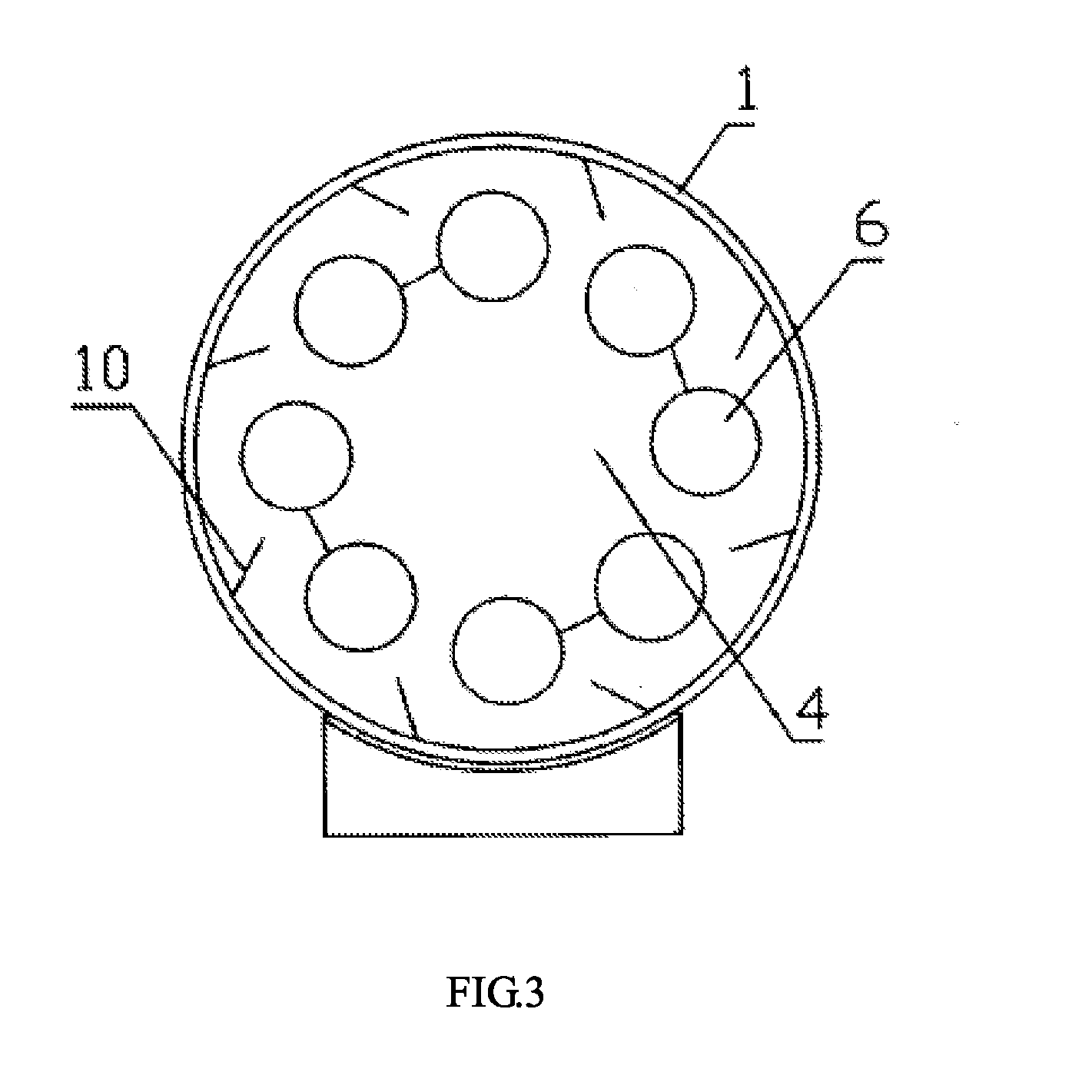
[0023]Referring to FIG. 2 and FIG. 3, a coal decomposition equipment comprises an airtight kiln body 1 with an inlet 2 and an outlet 3. The kiln body 1 is a horizontal and rotary kiln. A flame gas pipeline heating facility is set in the kiln body 1 and a channel 4 for impelling and decomposing coal is formed between the flame gas pipeline heating facility and an inner wall of the kiln body. A coal decomposition gas collecting pipe 5 is provided on the kiln body 1 to communicate with the channel 4, and an impelling board 10 is set in the inner wall of the kiln body 1. The flame gas pipeline heating facility includes a flame gas heat dissipation pipe 6 and a combustor chamber 7. The flame gas heat dissipation pipe 6 and the combustor chamber 7 communicate with a fuel supply pipe 8 and an air supply pipe 9. The flame gas heat dissipation pipe consists of multiple parallel close-packed pipes or tube mesh close-packed pipes so that the produced heat will be sufficiently transferred to th...

embodiment 3

[0024]Referring to FIG. 4, a coal decomposition equipment comprises an airtight kiln body 1 with an inlet 2 and an outlet 3. The kiln body 1 is an up-draft and rotary kiln. A flame gas pipeline heating facility is set in the kiln body 1 and a channel 4 for impelling and decomposing coal is formed between the flame gas pipeline heating facility and an inner wall of the kiln body. A coal decomposition gas collecting pipe 5 is provided on the kiln body 1 to communicate with the channel 4, and an impelling board 10 is set in the inner wall of the kiln body 1. The flame gas pipeline heating facility includes a flame gas heat dissipation pipe 6. The flame gas heat dissipation pipe 6 communicates with a combustor chamber 7, a fuel supply pipe 8 and an air supply pipe 9, which are all set outside of the kiln body 1. The flame gas heat dissipation pipe consists of multiple parallel close-packed pipes or tube mesh close-packed pipes so that the produced heat will be sufficiently transferred t...


PUM


Abstract

The invention discloses a coal decomposition equipment including an airtight kiln body with an inlet and an outlet, wherein a flame gas pipeline heating facility is set in the kiln body and a channel for impelling and decomposing coal is formed between the flame gas pipeline heating facility and an inner wall of the kiln body; and a coal decomposition gas collecting pipe is provided on the kiln body to communicate with the channel. Since the present invention makes the vast thermal conduction produced by the flame gas pipeline heating facility and radiate to the coal power in the coal substance impel decomposition channel. The pulverized coal fully absorbs the heat so as to be heated and decomposed to the gas, coal tar gas and coal with a higher heat-value in the channel.

Description

FIELD OF THE INVENTION[0001]The invention relates to comprehensive utilization of coal substance for saving energy and emission reduction, particularly to a coal decomposition equipment.BACKGROUND OF THE INVENTION[0002]In conventional technology, coal is used to produce coal gas, natural gas, or used to produce gas by coking at high temperature, medium temperature or low temperature. However, the above-mentioned technology is required to block pulverized coal or sift lamp coal, as a result, it increases the cost of raw material, or cause the produced gas without a high heat value, a big additional value, and a significant economy and social benefits. The heating methods of furnace can be classified as external-heating style, internal heating style and hybrid-heating style. Specifically, the heating medium in external-heating furnace is not contact directly with raw materials and heat is introduced from furnace wall. The heating medium in the internal-heating furnace contacts with th...

Claims


Application Information

Patent Timeline
Patent Type & Authority Applications(United States)
IPC IPC(8): F27B5/16
CPCC10B47/30C10B47/32C10K1/04C10K1/02C10B53/04C10B23/00C10B57/08C10B7/00
Inventor ZHU, SHUCHENGWANG, XIBINHUANG, XIANGYUNCAO, GUOCHAOLIU, WEI
Owner ZHU SHUCHENG
Why Eureka
Try Eureka