Carotid sheath with flexible distal section

a technology of flexible distal section and carotid sheath, which is applied in the direction of catheters, coatings, etc., can solve the problems of difficult positioning of such a sheath or guiding catheter, difficult to access the common carotid artery, and more invasive and potentially life-threatening procedures of surgical endarterectomy, etc., to achieve enhanced sheath tracking, greater flexibility, and enhanced rigidity

Active Publication Date: 2012-12-06
FISCHELL INNOVATIONS
View PDF7 Cites 46 Cited by
  • Summary
  • Abstract
  • Description
  • Claims
  • Application Information

AI Technical Summary

Benefits of technology

[0005]The present invention is a thin-walled, flat wire reinforced sheath with a differential in sheath flexibility from the proximal portion to the distal portion of the sheath. Specifically, the carotid sheath described herein would have a greater stiffness along most of its proximal length and more flexibility in the distal portion of the sheath in order to enhance sheath tracking over a guidewire, a diagnostic catheter, or a dilator. At this time, there is no sheath that exists that has a comparatively long (about 75 cm) and stiff proximal portion to provide “pushability” combined with a comparatively short (about 15 cm) distal portion that is highly flexible to provide ready tracking through the highly curved vascular anatomy that must often be navigated in order to successfully place a stent in a carotid stenosis. Such a novel carotid sheath would make stenting of a carotid stenosis a more predictably successful procedure.
[0006]Another important aspect of the present invention is the construction of the tubular shaft of the sheath. Existing sheaths have a wall thickness that is typically greater than 13 mils where 1.0 mil=0.001 inch. By using a flat wire helical coil with a wire thickness of approximately 1 mil to 3 mils, which coil has a very thin coating of plastic placed onto its inner and outer surfaces, it is possible to reduce the wall thickness of the tubular shaft to less than 7 mils and preferably to around 5 mils. Such a novel construction would reduce the outside diameter of the introducer sheath by approximately one French size compared to existing sheaths. Such a reduction in the diameter of the sheath would be advantageous in reducing the risk of bleeding at the groin that sometimes occurs after removal of sheaths having a larger outside diameter. Any method to decrease the requirement for surgical repair and/or a blood transfusion often needed for a major bleeding complication would be highly advantageous for the patient and could significantly decrease the morbidity, mortality and cost associated with catheterization procedures.
[0007]The present invention also envisions that the shaft of the sheath could employ a thin-walled, flat wire helical coil to be fabricated from a shape memory alloy such as Nitinol to prevent the possibility of kinking of the tubular shaft of the introducer sheath.

Problems solved by technology

The placement of such a sheath or guiding catheter can often be extremely challenging due to the tortuous course for access from the aortic arch into the common carotid artery.
This is particularly an issue when accessing the right common carotid artery, which typically arises as a proximal branch from the inominate artery.
Even with the best of equipment, it can be technically challenging, or even impossible to access the common carotid artery in order to stent a stenosis at that location when using any existing carotid sheath that has a uniform flexibility along its entire length.
If stenting is not possible, then the mo

Method used


Image

  • Carotid sheath with flexible distal section
  • Carotid sheath with flexible distal section
  • Carotid sheath with flexible distal section

Examples


Embodiment Construction

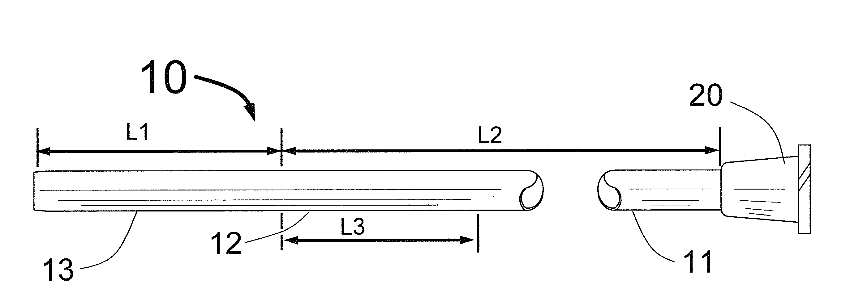
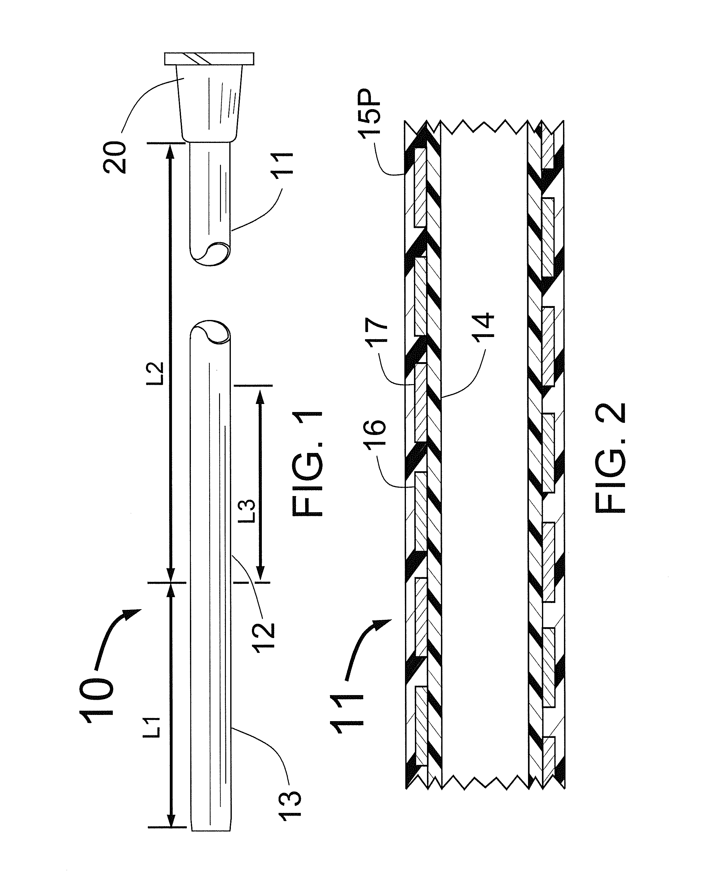
[0017]FIG. 1 shows a sheath 10 having a comparatively flexible distal portion 13 having a length L1, a comparatively long and stiff proximal portion having a length L2 and a comparatively short transitional section 12 with length L3. Typical lengths L1, L2 and L3 would be L1=15±5 cm, L2=75±10 cm and L3=3±3 cm. The total length of the carotid sheath should be about 90 cm. FIG. 1 also shows a Luer fitting at the proximal end of the sheath 10 which is typically used for injecting liquids through the sheath 10 or for connecting a Touhy-Borst fitting for performing carotid stenting. The Luer fitting with the Touhy-Borst fitting also allows for the passage of a dilator. Though it is not shown in FIG. 1, the present invention also envisions having a Touhy-Borst fitting fixedly attached at the sheath's proximal end instead of the Luer fitting. This would save one step for the operator by not requiring the attachment of a separate Touhy-Borst fitting to the Luer fitting.

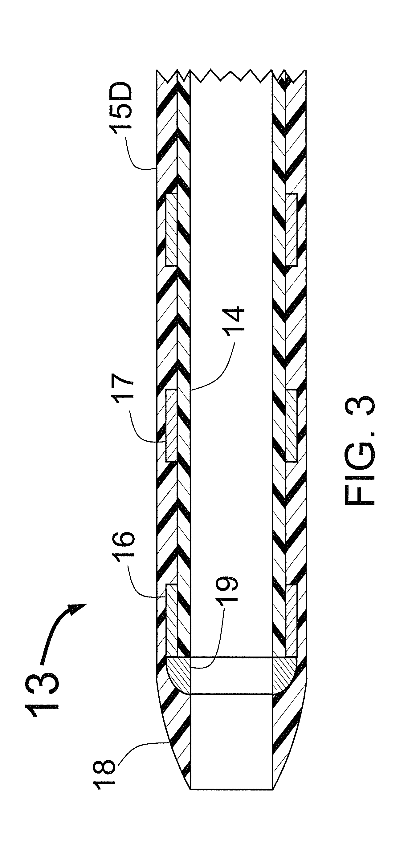
[0018]FIG. 2 shows a ...


PUM

PropertyMeasurementUnit
Lengthaaaaaaaaaa
Lengthaaaaaaaaaa
Diameteraaaaaaaaaa

Abstract

The present invention is a carotid sheath that has a proximal portion that is stiffer than the distal portion of the sheath as a result of the proximal portion having a higher durometer of the outer plastic coating of the sheath's proximal portion with a lower durometer for the plastic coating on the more flexible distal portion of the sheath. Another means to increase the flexibility of the sheath's distal portion compared to a stiffer proximal portion is by having a slightly smaller outside diameter for the outer plastic coating of the distal portion of the sheath. A more flexible distal portion of the sheath allows easier access for angiography, angioplasty or stenting when the sheath is used to access the tortuous path encountered when entering the carotid arteries.

Description

FIELD OF USE[0001]This invention is in the field of devices to assist in the placement of catheters through the skin to treat carotid artery obstructive disease.BACKGROUND OF THE INVENTION[0002]At the present time, physicians often treat carotid artery obstructive disease with the placement of a stent. This stent is typically placed in the internal carotid artery, in the common carotid artery, or spanning both arteries with the distal portion of the stent in the internal carotid artery and the proximal portion of the stent in the distal common carotid artery. The start of this procedure necessitates the placement of either a long sheath or a guiding catheter into the common carotid artery proximal to the carotid stenosis to be treated. The placement of such a sheath or guiding catheter can often be extremely challenging due to the tortuous course for access from the aortic arch into the common carotid artery. This is particularly an issue when accessing the right common carotid arte...

Claims


Application Information

Patent Timeline
IPC IPC(8): A61M25/00
CPCA61M25/0045A61M25/0054A61M25/005
Inventor FISCHELL, ROBERT E.LYNCH, TIMOTHY J.FISCHELL, TIM A.
Owner FISCHELL INNOVATIONS
Why Eureka
Try Eureka