Rolling bearing

Active Publication Date: 2012-12-13
EAGLE INDS
View PDF6 Cites 10 Cited by
  • Summary
  • Abstract
  • Description
  • Claims
  • Application Information

AI Technical Summary

Benefits of technology

[0029]The rolling bearing of the present invention exhibits the following exceptional effects.
[0030](1) The generation of mist and particulate is prevented, pressure fluctuations and vacuum quality deterioration on the vacuum side are prevented, and magnetic fluid sealing device deterioration is prevented, or problems such as high-temperature sagging and high torque due to the use of grease can be eliminated by having a magnet for holding in a lubrication portion of the rolling bearing a lubricating magnetic fluid for lubricating the lubrication portion be provided on at least one side of an outer race of the rolling bearing, and by having an annular yoke made of a magnetic material loosely fitted to a rotating shaft be provided on the opposite side of the magnet relative to the outer race.
[0031](2) A magnetic circuit can be formed sufficiently and easily by having the rotary shaft be formed from a magnetic material, and a magnetic circuit produced when the lubricating magnetic fluid is retained by the lubrication portion be formed by the magnet, the yoke,

Problems solved by technology

However, in Prior Art 1, the grease usually mixes with the thickeners in the base oil, and this causes some oil separation.
A problem is presented in that the pressure resistance and vacuum properties are adversely affected, and the life of the magnetic fluid sealing device 101 is reduced (referred to below as the “Problem 1”).
This may damage the bearing

Method used


Image

  • Rolling bearing
  • Rolling bearing
  • Rolling bearing

Examples


Example

1st Embodiment

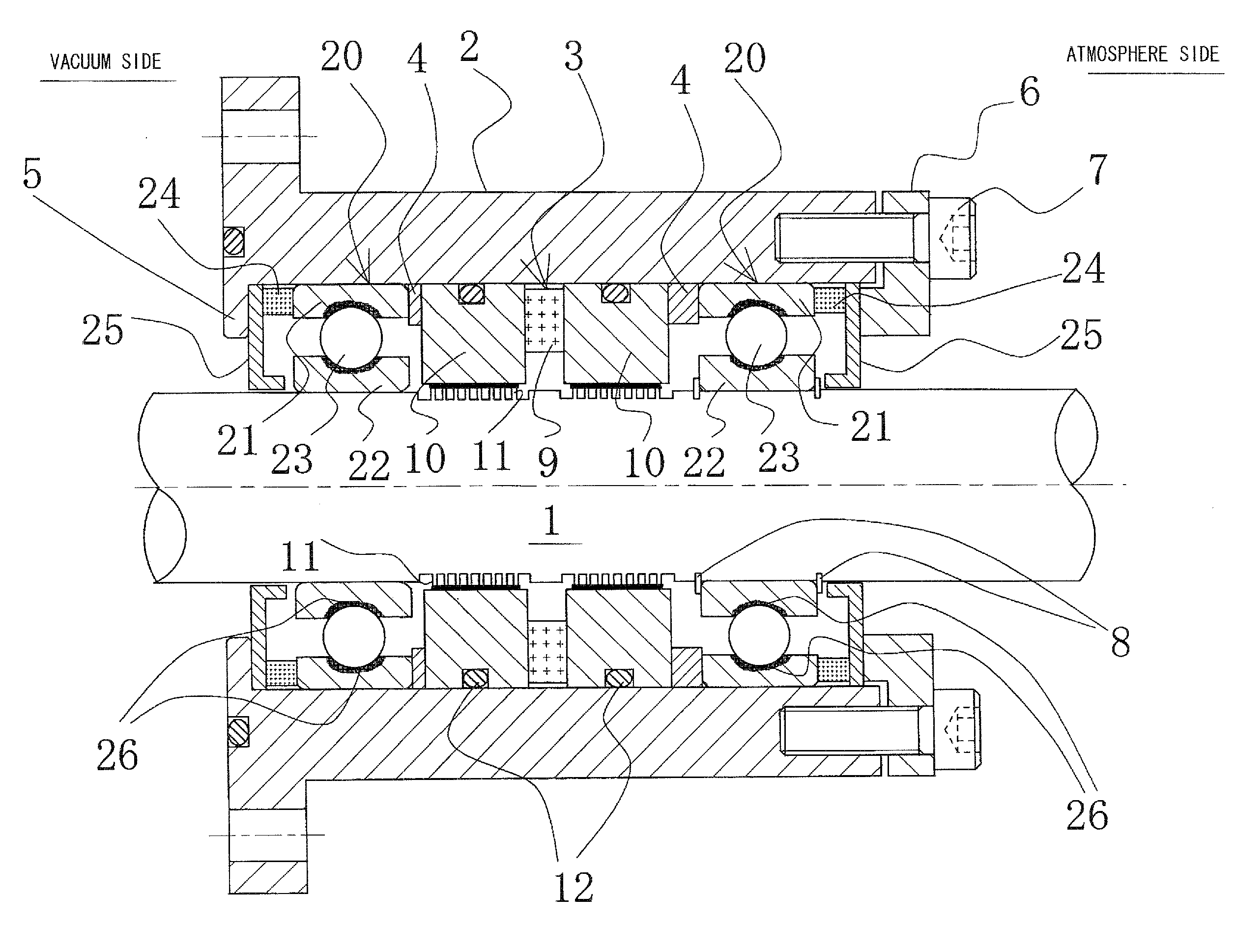
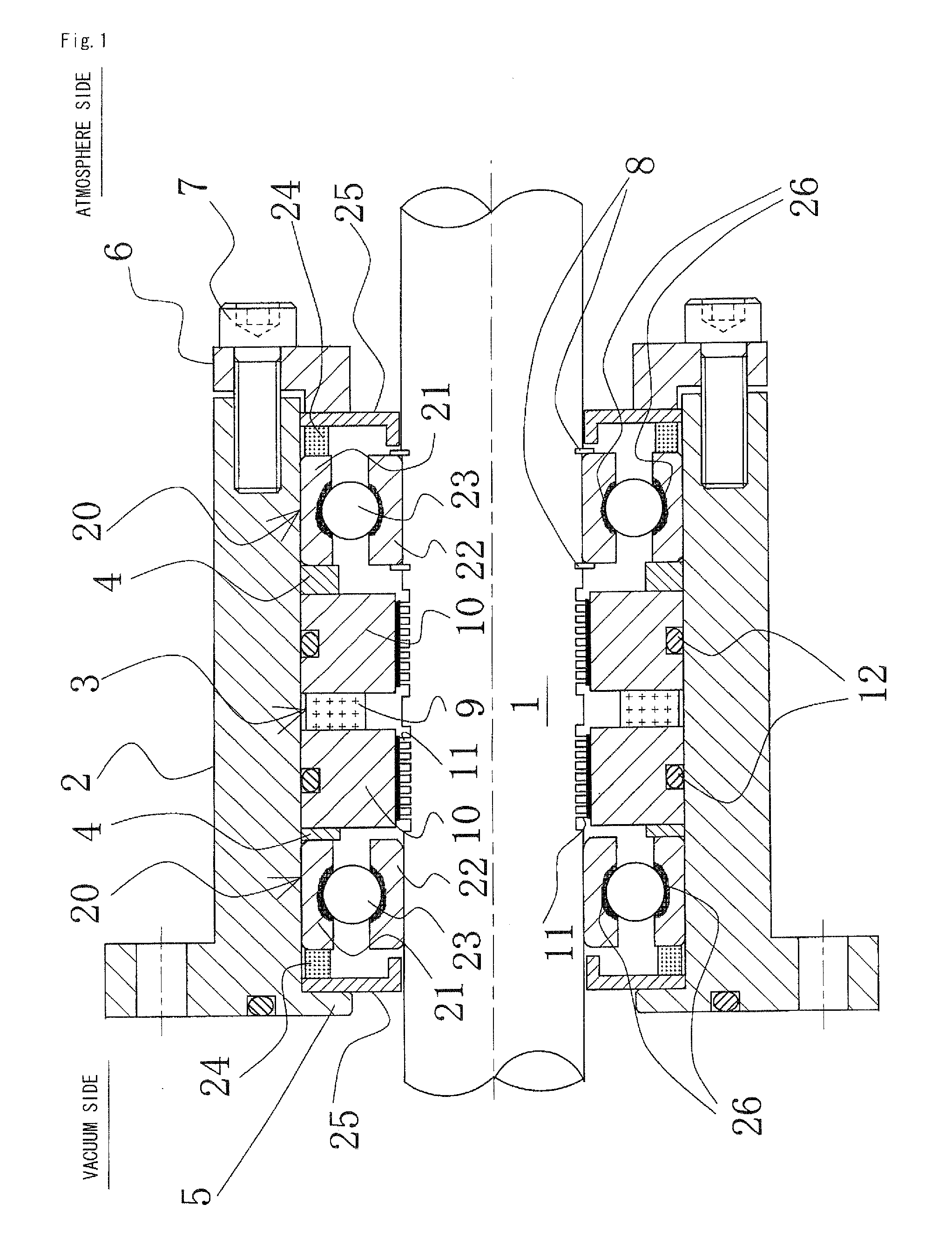
[0048]FIG. 1 is a front cross-sectional view showing an example in which a rolling bearing according to a first embodiment of the present invention is applied to a bearing device with a magnetic fluid seal, and FIG. 2 is a front cross-sectional view showing an example in which a rolling bearing according to the first embodiment of the present invention is applied to a bearing device without a magnetic fluid seal. Also, FIG. 3 is a front cross-sectional view used to describe a rolling bearing 20 according to a first embodiment of the present invention.

[0049]In FIGS. 1 and 2, the vacuum side is on the left and the atmosphere side is on the right. However, as shall be apparent, a rolling bearing of the present invention can also have the atmosphere on both sides, or the vacuum on both sides.

[0050]In FIG. 1, a bearing device is installed between a housing 2 and a rotary shaft 1, the bearing device sealing the space between the rotary shaft 1 and the housing 2, and rotatabl...

Example

[0055]In FIG. 1 and FIG. 2, the rolling bearing 20 according to the first embodiment of the present invention is a bearing in which are employed bail bearings, rolling bearings, or another rolling element. An outer race 21 is immobilized on the housing 2, and an inner race 22 is immobilized on the rotating shaft 1. Balls 23 are fitted between the outer race 21 and the inner race 22.

[0056]Magnets 24 are provided on the vacuum-side surface of the outer race 21 of the rolling bearing 20 on the vacuum side, and on the atmosphere side of the outer race 21 of the rolling bearing 20 on the atmosphere side. In addition, an annular yoke 25 made of a magnetic material and loosely fitted to the rotary shaft 1 is provided on the opposite side of the magnets 24 relative to the outer races 21. In FIG. 1, having a magnetic trap composed of the magnet 24 and the yoke 25 provided on both the vacuum side and the atmosphere side of the rolling bearings 20 enables the release of particulate in the vacu...

Example

[0067]The basic structure of the rolling bearing 20 according to the second embodiment is similar to that according to the first embodiment. In FIG. 4, components denoted by the same reference numerals as those in FIG. 3 are identical to those in FIG. 3. The following is primarily an explanation of the portions differing from those in the first embodiment.

[0068]In FIG. 4, the ring-shaped yoke 25 has an L-shaped cross-section as in the first embodiment. The portion contacting the magnet 24 is the vertical portion 25-1 of the L-shape, and the portion facing the surface of the rotary shaft 1 is the horizontal portion 25-2 of the L-shape. The horizontal portion 25-2 extends toward the inner race 22.

[0069]In FIG. 4 (a), a sawtooth-shaped uneven portion 27 is formed on the surface of the horizontal portion 25-2 of the yoke 25 facing the surface of the rotary shaft 1.

[0070]In FIG. 4 (b), a square-thread-shaped uneven portion 28 is formed on the face of the horizontal portion 25-2 of the yo...


PUM


Abstract

A rolling bearing used in a power transmission device for transmitting power such as turning force, includes a magnet for holding in a lubrication portion of the rolling bearing. A lubricating magnetic fluid for lubricating the lubrication portion is provided on at least one side of an outer race of the rolling bearing, and an annular yoke made of a magnetic material loosely fitted to a rotating shaft is provided on the opposite side of said magnet relative to said outer race.

Description

TECHNICAL FIELD[0001]The present invention relates to a rolling bearing and, more specifically, to a rolling bearing employing a magnetic fluid suitable for use in a vacuum field for a device for manufacturing semiconductors, FPD, solar cells, and the like.BACKGROUND ART[0002]In semiconductor manufacturing devices and the like, for example, a wafer is arranged inside a reaction chamber held in a high vacuum state by a vacuum pump, a reaction gas is introduced, and a thin film is formed using CVD or the like. A work piece has to be transported inside the reaction chamber in a sealed state. In a transporting mechanism used to perform such a task, there has to be a complete, air-tight partition inside the reaction chamber between the arm portion actually holding the work piece and the drive mechanism for transmitting power from outside of the reaction chamber to the arm portion. Also, the generation of dust and the like has to be maximally suppressed on the reaction chamber side. As a ...

Claims


Application Information

Patent Timeline
IPC IPC(8): F16C33/66H01F7/02
CPCF16J15/43F16C33/7886F16C19/54F16C33/6644F16C19/06F16C33/765F16C33/82F16C2210/06F16C33/66
Inventor HONDA, SHIGEKI
Owner EAGLE INDS
Why Eureka
Try Eureka