Grinding device for machine based grinding of rotor blades for wind energy systems

a technology of wind energy system and grinding device, which is applied in the direction of grinding machine components, manipulators, grinding machines, etc., can solve the problems of uneconomical use of robots and inability to conventionally grind by hand, and achieve the effect of increasing effort and speeding up the execution speed

Inactive Publication Date: 2012-12-20
JOST GMBH & CO KG
View PDF14 Cites 50 Cited by
  • Summary
  • Abstract
  • Description
  • Claims
  • Application Information

AI Technical Summary

Benefits of technology

[0015]Preferably, the cleaning device cleans the grinding surface by means of a nozzle for blowing on of pressurized air and / or a device for the suchtion of grinding dust and / or a brush for brushing the grinding surface. These three measures, lead either on their own or in any combination with each other to the fact that also the abrasion of viscoplastic coatings is removed nearly completely from the grinding surface of the grinding means and cannot adhere there and cannot clog the grinding surface. By the active cleaning of the cleaning surface, the life time of the grinding means is increased but also the quality of the grinding task.
[0029]Preferably, the industrial robot is also used for lacquering the rotor blades. By doing so the investment costs of the entire system is reduced to a minimum, wherein in one system lacquering of a rotor blade as well as the grinding and the dedusting of the rotor blade respectively is carried out with the same industrial robot that has only to exchange the necessary tools between the single process steps. Also such an exchange can be carried out automatically. According to this the entire coating processes, including grinding and dedusting of a rotor blade is reduced to a fraction of time, compared with conventional systems in which it has to be ground manually and often also to be lacquered manually. According to this the manufacturing times as well as the manufacturing costs are reduced by the grinding device according to the invention.

Problems solved by technology

This was not possible for conventional grinding means, since a use of a robot was uneconomical because of the fast clogging of the grinding means and the high exchange rates of the grinding means.

Method used


Image

  • Grinding device for machine based grinding of rotor blades for wind energy systems
  • Grinding device for machine based grinding of rotor blades for wind energy systems
  • Grinding device for machine based grinding of rotor blades for wind energy systems

Examples


Embodiment Construction

[0040]In the following preferred embodiments of the invention are described with reference to the figures. Single features of the herein described embodiments can be combined with other embodiments of the invention.

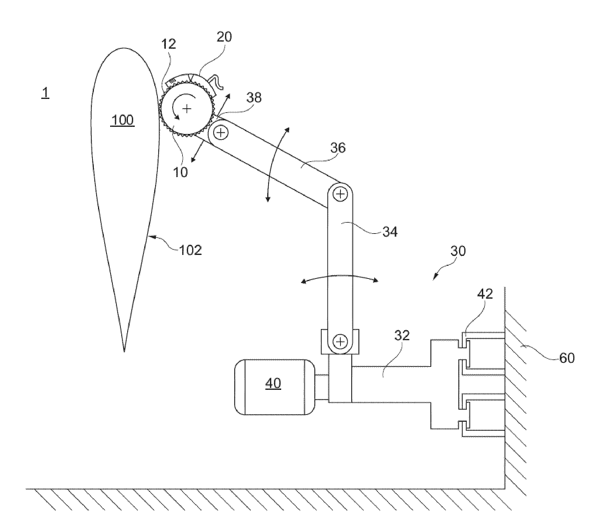
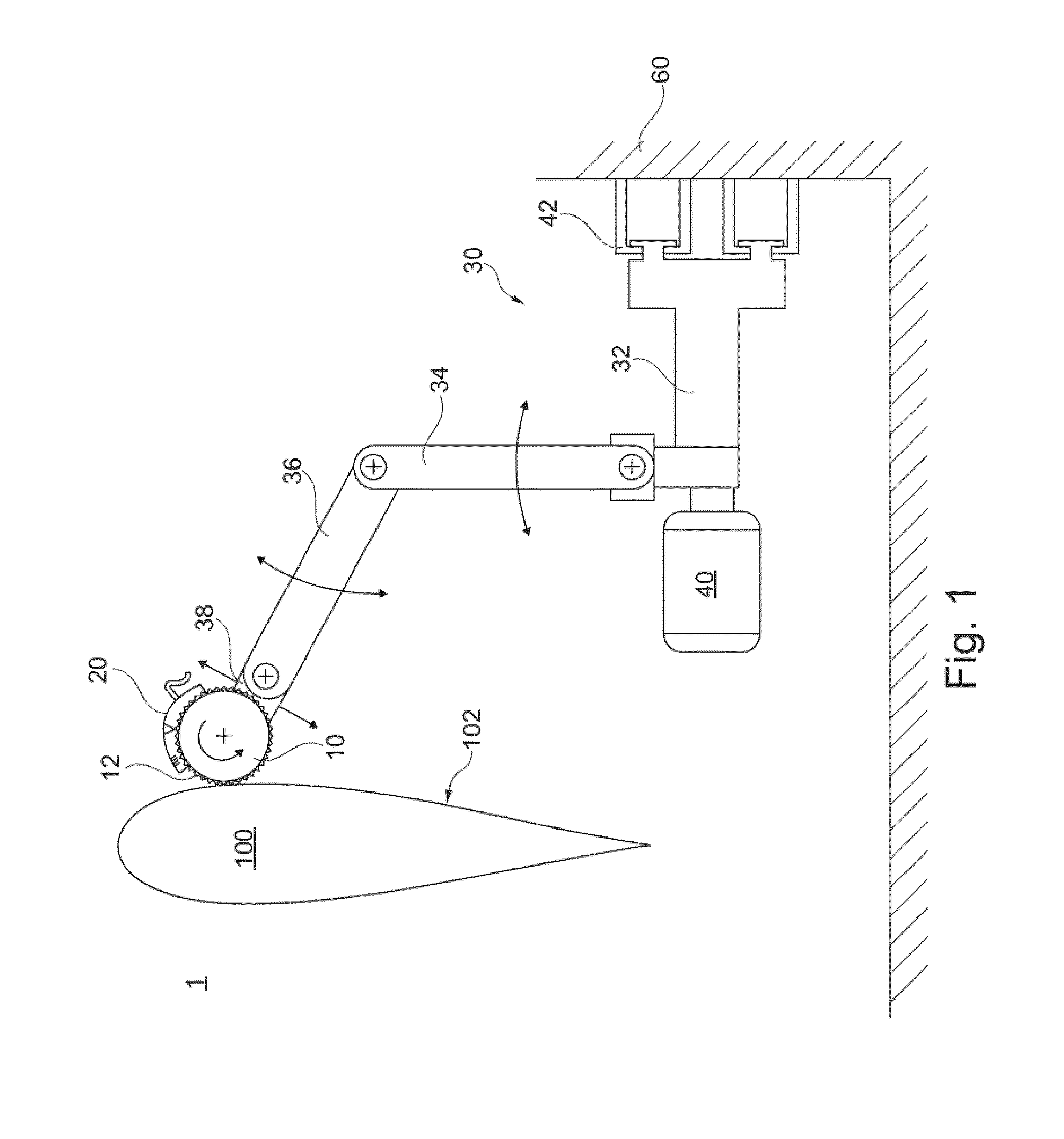
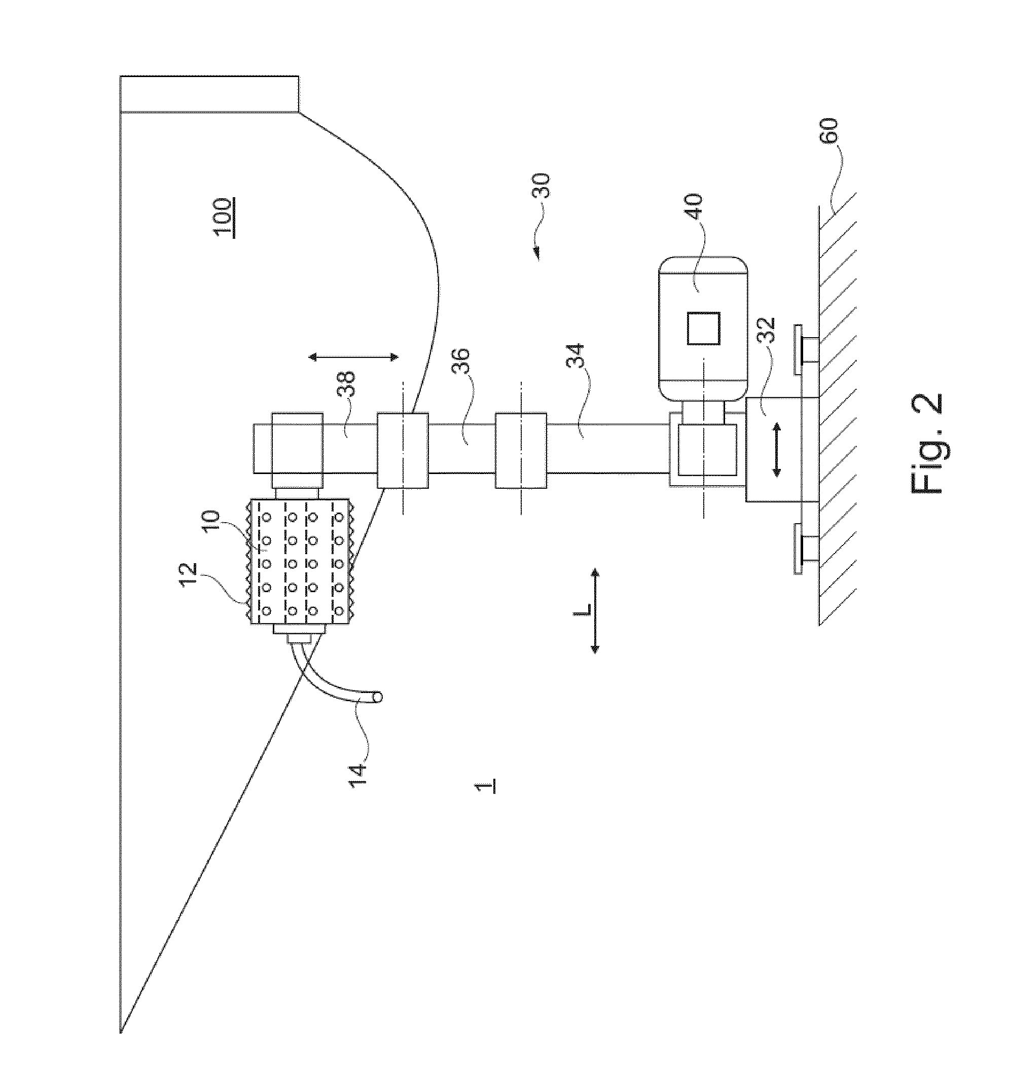
[0041]FIGS. 1 and 2 show a front view and a top view of a grinding device 1 for machine-based grinding of rotor blades 100. In FIG. 1 an industrial robot 30 is arranged on the right hand side of the rotor blade 100 at the wall 60 of a building, wherein it is possible to move the industrial robot 30 in the longitudinal direction. The industrial robot 30 can move by means of an undercarriage 32 at the wall 60 along a longitudinal axis L of the rotor blade 100 at wall tracks 42. The industrial robot 30 is only shown in a symbolic manner and can be every industrial robot that is appropriate for the task that is described in the following. As shown, the industrial robot 30 comprises an undercarriage 32, a drive motor 40, a first arm 34, that is attached to the undercarriage 32...


PUM


Abstract

Grinding device 1 for machine-based grinding of rotor blades 100 for wind energy systems, comprising at least one industrial robot 30 and a grinding unit 10, 50, 70 that is guided by the industrial robot 30, wherein the grinding unit 10, 50, 70 comprises a grinding means, 12, 52 and a cleaning device 20, that cleans the grinding means 12, 52 at its grinding surface 64, 53.

Description

1. FIELD OF THE INVENTION[0001]The present invention relates to a grinding device for a machine based grinding of rotor blades for wind energy systems. By the use of the grinding device, grinding tasks can be automated during the manufacturing and during the maintenance of rotor blades.2. PRIOR ART[0002]The use of wind force for the energy generation is seen as one of the most environmentally compatible forms of winning energy. Therefore, wind energy systems are used, that comprise a rotor that drives a generator and that is supported rotatably at a mast. The loads, that effect on the parts in particular the rotor blades of a wind energy system is however very high.[0003]Atmospheric influences, like for instance wind, water, hail, UV-radiation, erosion- and bending-loads lead to highest requirements for the material of the rotor blades. The correct operation and the surface quality are relevant for the effectivity and economic efficiency of wind energy systems. Thus, rotor blades co...

Claims


Application Information

Patent Timeline
Patent Type & Authority Applications(United States)
IPC IPC(8): B24B19/14B24B49/10B24B53/00B24B21/16
CPCB24B19/14B24B21/16B24B27/0038B25J11/0065B24B53/007B24B55/06B24D9/02B24B27/0061
Inventor JOSI, PETER
Owner JOST GMBH & CO KG
Why Eureka
Try Eureka