Processing system for processing specimens using acoustic energy

a processing system and acoustic energy technology, applied in the field of methods and systems for analyzing specimens using energy, can solve the problems of difficult to diffuse processing liquid through the tissue, no standard procedures, staining issues, etc., and achieve the effects of improving processing quality, reducing processing times, and improving processing consistency

Active Publication Date: 2012-12-27
VENTANA MEDICAL SYST INC
View PDF6 Cites 16 Cited by
  • Summary
  • Abstract
  • Description
  • Claims
  • Application Information

AI Technical Summary

Benefits of technology

[0014]At least some embodiments are directed to methods and systems for analyzing a specimen. The specimen can be analyzed based on its properties. These properties include acoustic properties, mechanical properties, optical properties, or the like that may be static or dynamic during processing. In some emb...

Problems solved by technology

Currently, there are no standard procedures for fixing tissues and this lack of organization leads to a variety of staining issues both with primary and advanced stains.
If the tissue is over-fixed, it may be difficult to diffuse processing liquids through the tissue due to the extensive network of cross-linked molecules.
This can result in inadequate penetration of the processing liquids.
If the processing liquid is a stain, slow diffusion rates can cause uneven and inconsistent staining.
These types of problems can be increased if the stain has relatively large molecules.
If the tissue is under-fixed, the tissue may be susceptible to severe morphology problems or autocatalytic destruction.
Severe morphology problems result from an incomplete network of cross-linked molecules and subsequent shrinking of cells, nuclei and cytoplasm during dehydration steps.
Autocatalytic destruction can result in loss of tissue structure, cell structure and tissue morphology, especially if the tissue is not processed within a relatively short period of time.
Accordingly, under-fixed tissue may be unsuitable for examination and is often discarded.
The rate of immu...

Method used


Image

  • Processing system for processing specimens using acoustic energy
  • Processing system for processing specimens using acoustic energy
  • Processing system for processing specimens using acoustic energy

Examples


Embodiment Construction

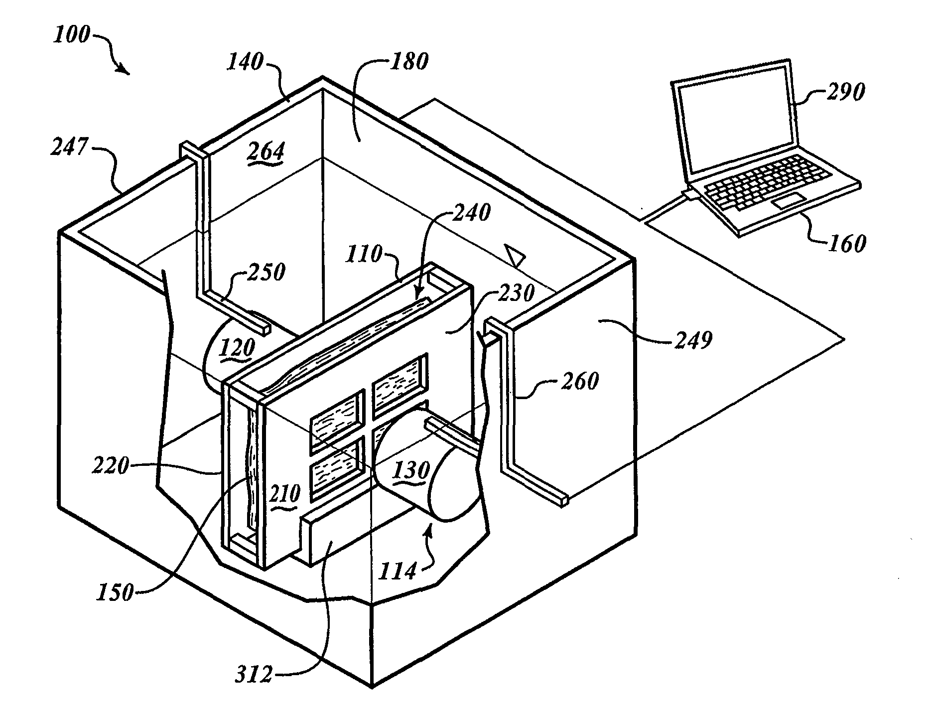
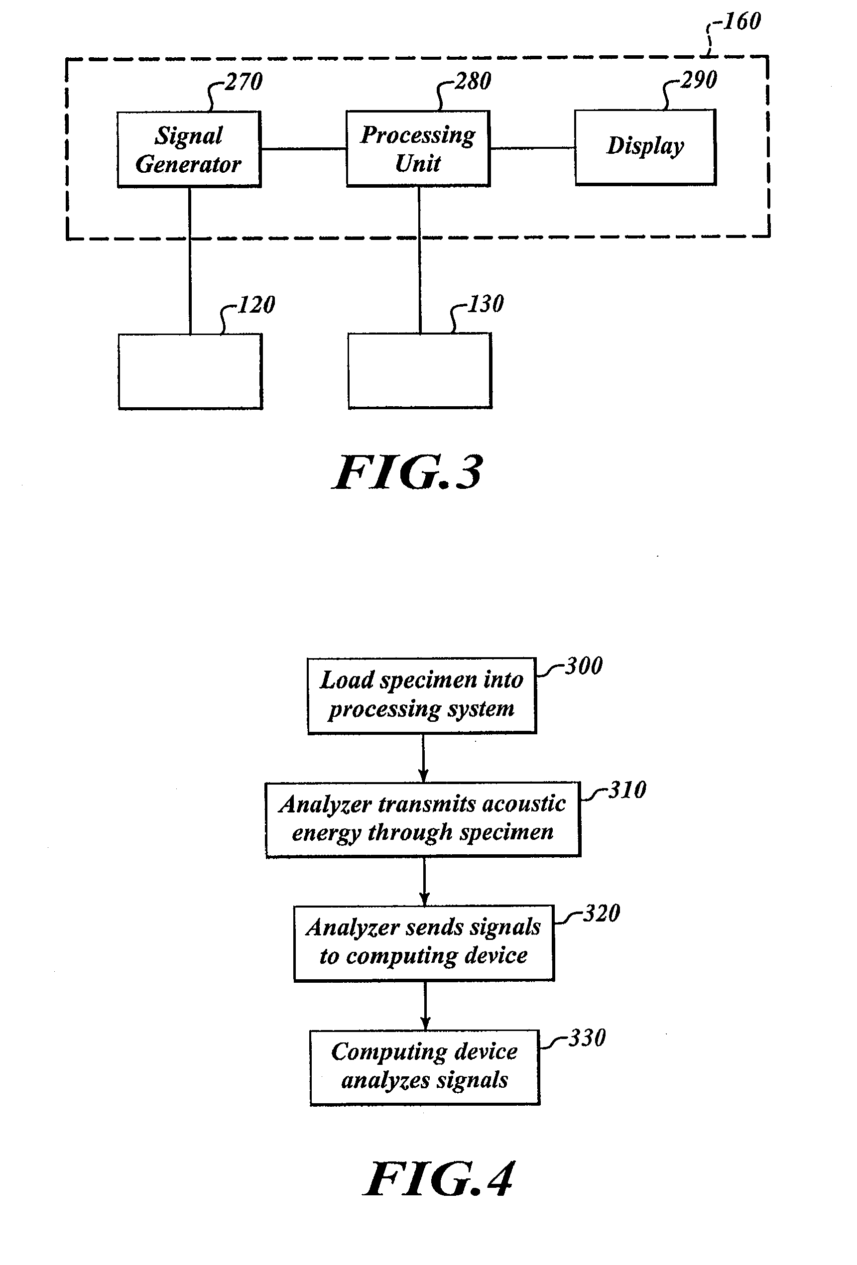
[0082]FIG. 1 shows a processing system 100 for processing specimens. The processing system 100 includes a specimen holder 110, a container 140, and an analyzer 114 positioned in the container 140. The analyzer 114 includes a transmitter 120 and a receiver 130. A computing device 160 is communicatively coupled to the analyzer 114.

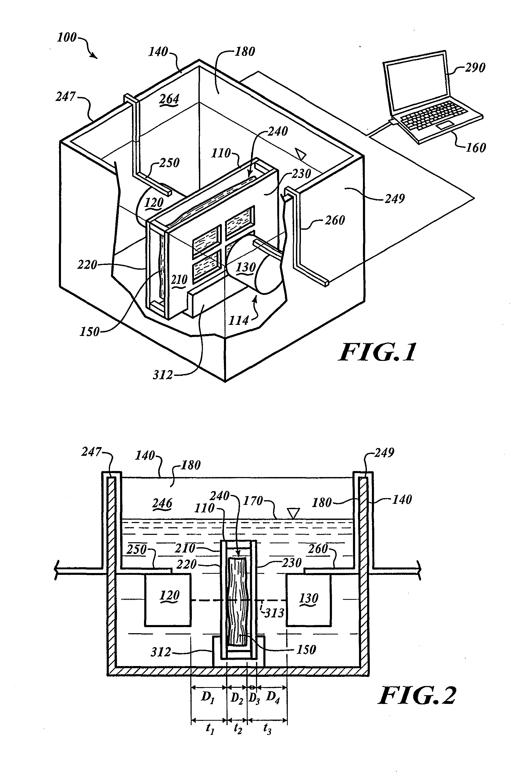
[0083]FIG. 2 shows the container 140 with a chamber 180 filled with a processing media 170. The specimen holder 110, the transmitter 120, and the receiver 130 are submerged in the processing media 170. To fix a tissue specimen 150, the processing media 170 can be a fixative that diffuses through the specimen 150.

[0084]To analyze the specimen 150, the computing device 160 causes the transmitter 120 to output energy that passes through the specimen 150. The receiver 130 can receive the energy and can send signals to the computing device 160 in response to the received energy. The computing device 160 analyzes those signals to monitor processing. Once processin...


PUM


Abstract

A method for fixing a biological sample includes delivering energy through a biological sample that has been removed from a subject, while fixing the biological sample. A change in speed of the energy traveling through the biological sample is evaluated to monitor the progress of the fixation. A system for performing the method can include a transmitter that outputs the energy and a receiver configured to detect the transmitted energy. A computing device can evaluate the speed of the energy based on signals from the receiver.

Description

CROSS-REFERENCE TO RELATED APPLICATION[0001]This application claims the benefit under 35 U.S.C. §119(e) of U.S. Provisional Patent Application No. 61 / 310,653 filed on Mar. 4, 2010. This provisional application is incorporated herein by reference in its entirety.BACKGROUND[0002]1. Technical Field[0003]The present invention relates generally to methods and systems for analyzing specimens using energy. More specifically, the invention is related to methods and systems for analyzing tissue specimens using acoustic energy.[0004]2. Description of the Related Art[0005]Preservation of tissues from surgical procedures is currently a topic of great importance. Currently, there are no standard procedures for fixing tissues and this lack of organization leads to a variety of staining issues both with primary and advanced stains. The first step after removal of a tissue sample from a subject is to place the sample in a liquid that will suspend the metabolic activities of the cells. This process ...

Claims


Application Information

Patent Timeline
IPC IPC(8): G01N1/30C12M1/42G01N29/44G01N29/024G01N29/07G01N29/12
CPCG01N29/024G01N2291/02475G01N2291/02466G01N29/4427G01N33/4833G01N1/30G01N29/07
Inventor OTTER, MICHAELCHAFIN, DAVIDPIERSON, ABBEYTAFT, JEFFERSON CURTIS
Owner VENTANA MEDICAL SYST INC
Why Eureka
Try Eureka