Supercharge Your Innovation With Domain-Expert AI Agents!

Signal value storage circuitry with transition detector

a technology of signal value storage and transition detector, which is applied in the field of data processing systems, can solve the problems of significant performance penalty, significant increase in the set up time of a dff employing these error detection and correction techniques, and uncertainty in the timing of their operation, so as to simplify the control of the transition detector circuitry, reduce uncertainty, and reduce the effect of uncertainty

Active Publication Date: 2013-01-03
ARM LTD
View PDF2 Cites 7 Cited by
  • Summary
  • Abstract
  • Description
  • Claims
  • Application Information

AI Technical Summary

Benefits of technology

This patent describes a circuit that helps detect and correct errors in a data transmission system. It uses two delayed clock signals to accurately detect and locate errors in a processing signal. The circuit has a simple design and can be easily verified, and it helps improve the speed and reliability of data transmission.

Problems solved by technology

If a transition occurs in the input signal to the DFF after the signal has been captured into the DFF and during the error detection period, then this indicates a late arriving signal at the DFF and corresponds to an error that should trigger an error recovery operation.
A problem with this type of DFF is that the transition detector monitors the input of the master latch to observe the late arriving signal.
Various paths within the DFF employing this technique contribute to the uncertainty in the timing of its operation.
All this increase in margin leads to a significant increase in the set up time of a DFF employing these error detection and correction techniques compared to the set up time of the underlying DFF not using such techniques.
This is a significant performance penalty.

Method used


Image

  • Signal value storage circuitry with transition detector
  • Signal value storage circuitry with transition detector
  • Signal value storage circuitry with transition detector

Examples


Embodiment Construction

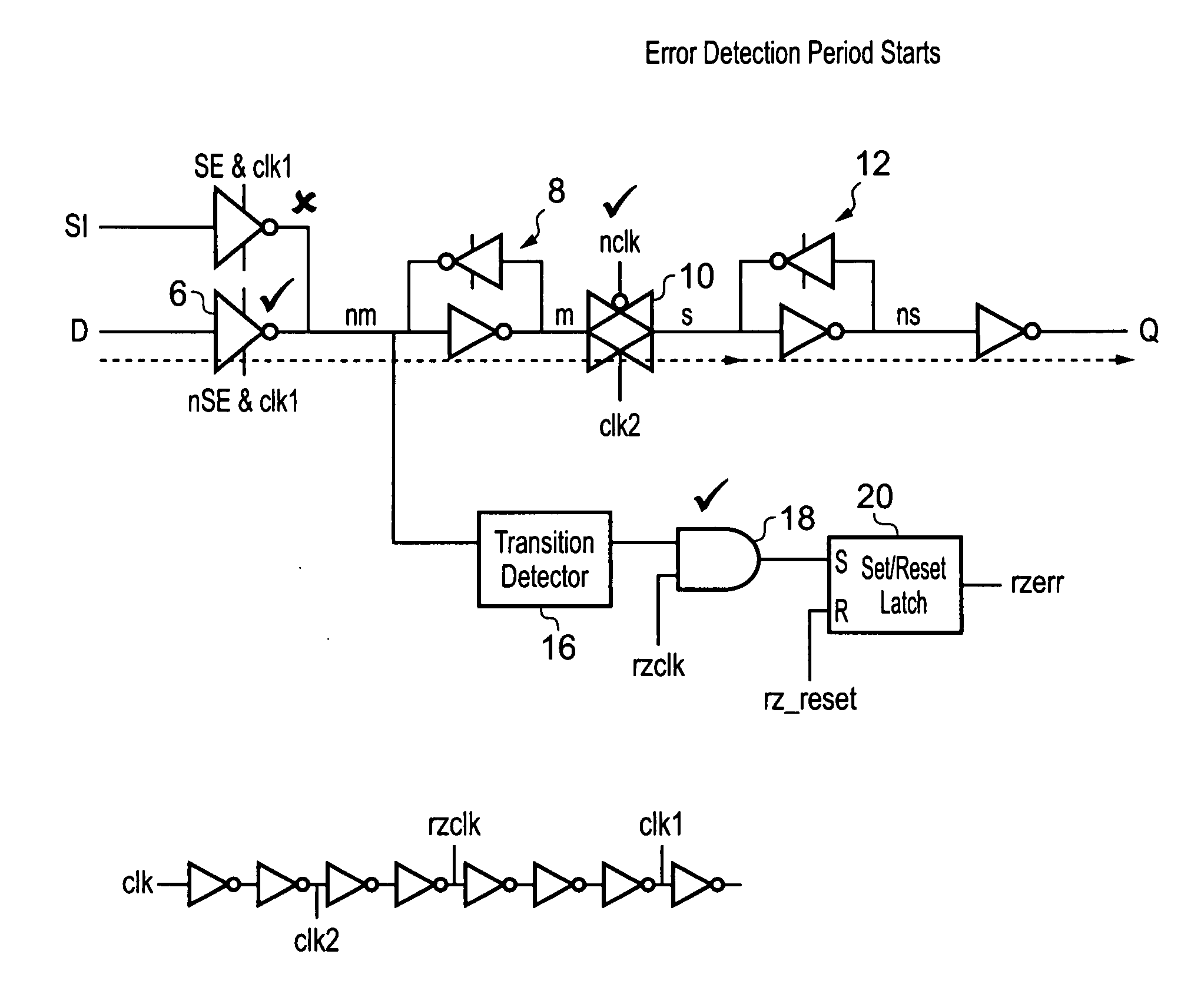
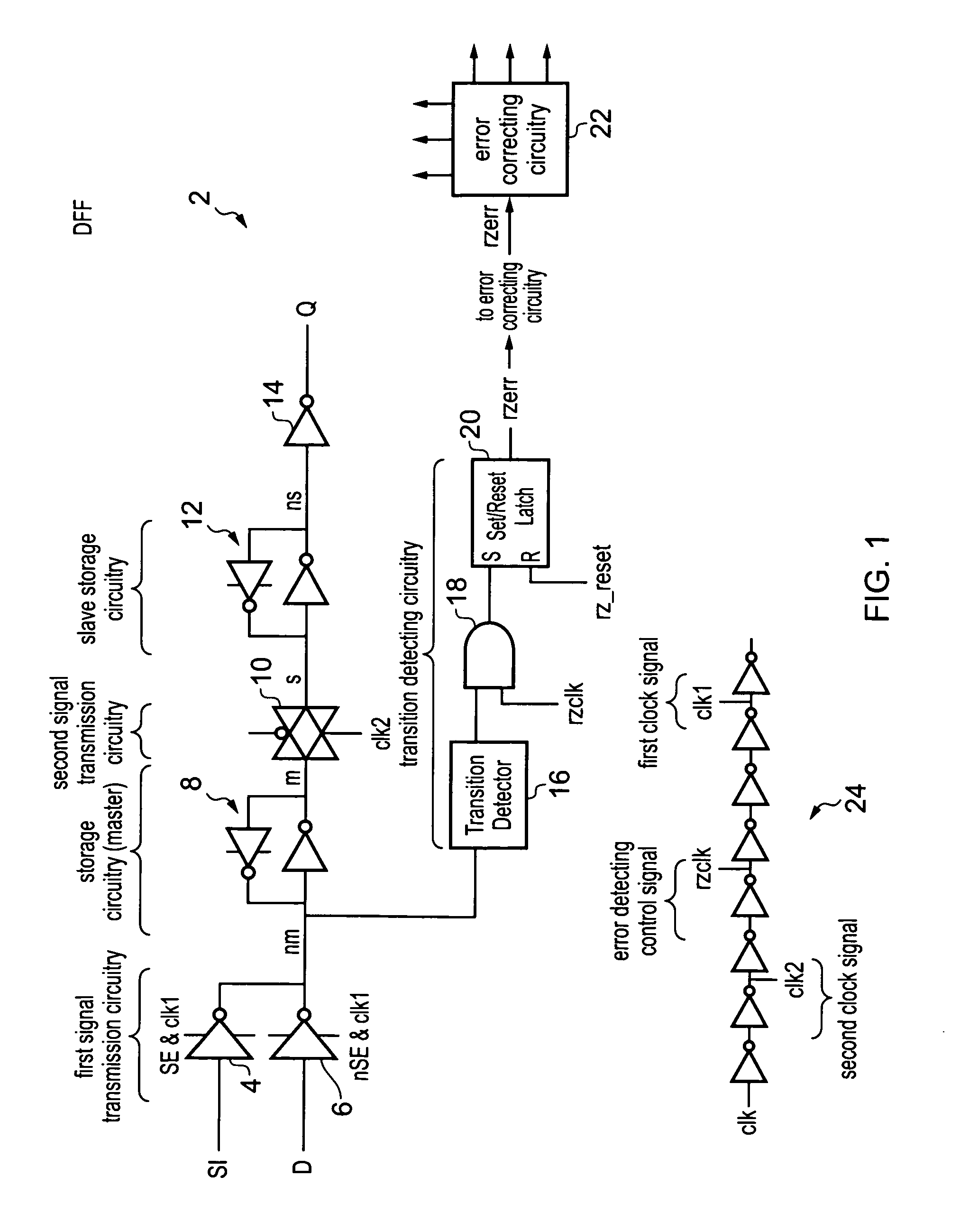
[0052]FIG. 1 schematically illustrates signal value storage circuitry in the form of a D-type flip flop 2. This includes first signal transmission circuitry in the form of two tristate inverters 4, 6 controlled by a combination of a first clock signal clk1 and a scan enable signal se. Storage circuitry 8 serves as part of a master latch and is formed of a cross-coupled inverter pair (the feedback inverter is a tri-state inverter which is enabled when clk1 is low). Second signal transmission circuitry in the form of a transmission gate 10 is connected to the storage output of the master storage circuitry 8. Slave storage circuitry 12 receives the output from the transmission gate 10 and passes this via an inverter 14 to form the output signal Q from the D-type flip flop 2. The transmission gate 10 is controlled using a second clock signal nclk / bclk.

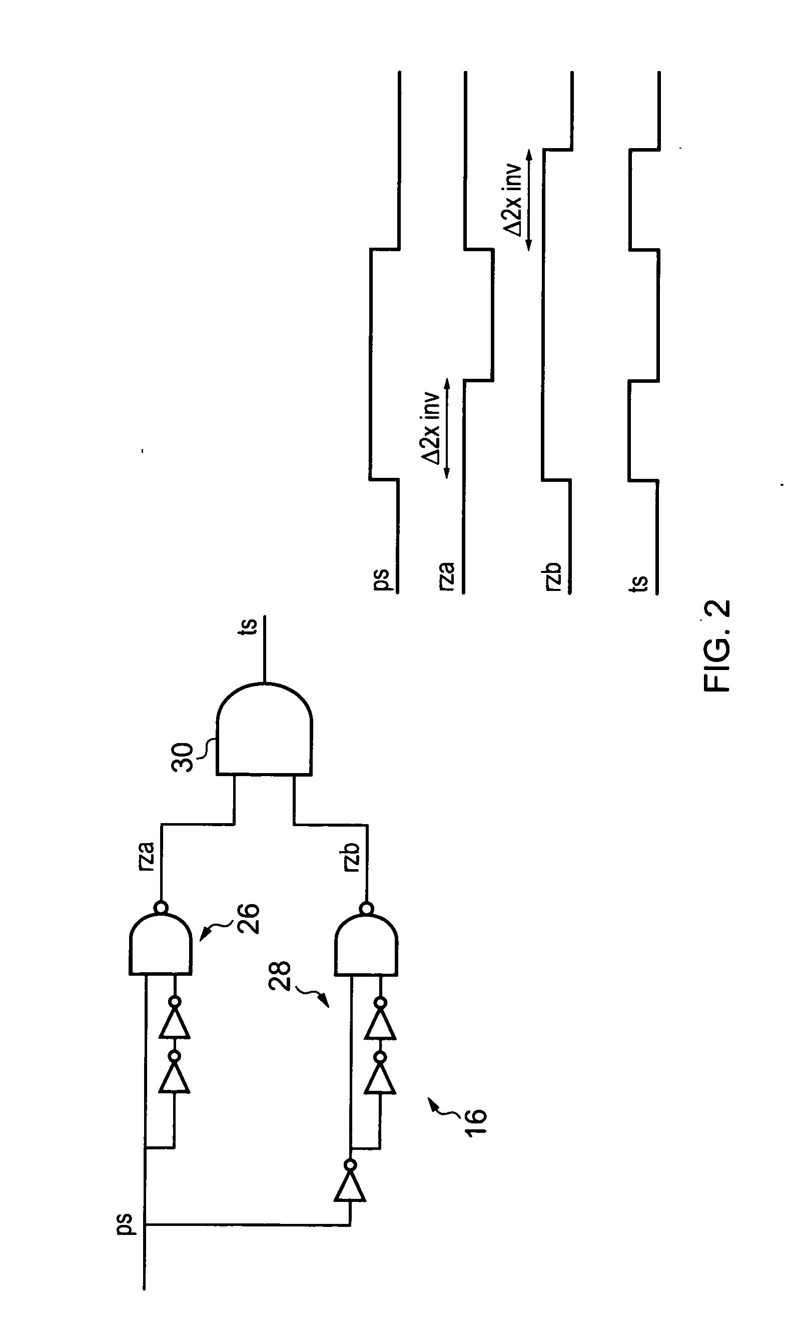
[0053]Transition detector circuitry 16 is connected to the input node nm of the master storage circuitry 8. The transition detector 16 as...


PUM


Abstract

A D-type flip-flop 2 includes tristate inverter circuitry 4, 6 passing a processing signal through to storage circuitry 8 from where the processing signal passes via a transmission gate 10 to slave storage circuitry 12. A transition detector 16 is coupled to the input node nm of the storage circuitry 8 and serves to generate an error signal if a transition is detected upon that input node during an error detecting period. Other forms of this technique may provide clock gating circuitry.

Description

BACKGROUND OF THE INVENTION[0001]1. Field of the Invention[0002]This invention relates to the field of data processing systems. More particularly, this invention relates to signal value storage circuitry including a transition detector.[0003]2. Description of the Prior Art[0004]It is known to provide signal value storage circuitry, such as D-type flip-flops (DFF), for use in storing signal values, such as signal values representing binary values. Such signal value storage circuitry may be used in many different places within a data processing system, such as for storing data values to be processed, control values for controlling such processing, program instructions to control processing and the like.[0005]It is known from WO-A-2004 / 084072 to provide a data processing system which is configured to operate at a finite non-zero error rate and includes error detection and recovery mechanisms. In this way, the operating frequency can be increased and / or the operating voltage reduced to ...

Claims


Application Information

Patent Timeline
IPC IPC(8): H03K19/00H03L7/00
CPCH03K3/0372H03K5/1534H03K3/0375H03K3/037H03K3/356
Inventor HOWARD, DAVID WILLIAMBULL, DAVID MICHAELDAS, SHIDHARTHA
Owner ARM LTD
Features
  • R&D
  • Intellectual Property
  • Life Sciences
  • Materials
  • Tech Scout
  • Unparalleled Data Quality
  • Higher Quality Content
  • 60% Fewer Hallucinations
Learn More