Carbon - lead blends for use in hybrid energy storage devices

Active Publication Date: 2013-01-03
BASF SE
View PDF12 Cites 74 Cited by
  • Summary
  • Abstract
  • Description
  • Claims
  • Application Information

AI Technical Summary

Benefits of technology

The present invention is about creating materials that can store and distribute energy. The invention involves blending carbon particles with lead particles to create a desirable electrochemical profile. The carbon particles can be any suitable material, such as activated carbon or ultrapure carbon. The carbon particles can also contain lead material. The resulting blend can be used in energy storage devices, such as batteries, and can exhibit improved performance. The invention also includes methods for making and using the blended materials.

Problems solved by technology

Conventional lead-acid energy storage devices may have limited active life and power performance.
Hybrid energy storage devices employing either carbon or lead-acid electrodes (but not their combination at the same electrode) may provide some improvement and advantages over conventional lead-acid devices; however, their active life, energy capacity and power performance can likewise be limited.
For example, lead-based positive electrodes often fail due to a loss of active lead dioxide paste from the current collector grid after multiple charge / discharge cycles.
The anodes of these devices also deteriorate upon multiple charge / discharge cycles because the discharge lead sulfate crystal size increases and leads to ‘densification’ of the negative plate resulting in reduced charge acceptance and loss of capacity.
This electrode failure is thought to be a result of secondary and tertiary side reactions caused by impurities in the carbon materials employed in these devices.
In addition, the low surface area of the electrodes and relatively high ion migration distances limits the power performance of these devices.
The negative electrodes typically will not wear out; but on the other hand, just as with lead acid storage batteries, the positive lead-based electrodes of ultracapacitor energy storage devices will typically fail first.
Those failures are generally the result of the loss of active lead dioxide paste shedding from the current collector grid as a consequence of spalling and dimensional change deterioration during charging and discharging cycles.
Although the need for improved carbon materials for use in hybrid lead-carbon energy storage devices has been recognized, such carbon material has yet to be developed.

Method used


Image

  • Carbon - lead blends for use in hybrid energy storage devices
  • Carbon - lead blends for use in hybrid energy storage devices
  • Carbon - lead blends for use in hybrid energy storage devices

Examples


example 1

Preparation of Dried Polymer Gel

[0284]A polymer gel was prepared by polymerization of resorcinol and formaldehyde (0.5:1) in water and acetic acid (75:25) and ammonium acetate (RC=25, unless otherwise stated). The reaction mixture was placed at elevated temperature (incubation at 45° C. for about 6 h followed by incubation at 85° C. for about 24 h) to allow for gellation to create a polymer gel. Polymer gel particles were created from the polymer gel and passed through a 4750 micron mesh sieve. The sieved particles were frozen by immersion in liquid nitrogen, loaded into a lyophilization tray at a loading of 3 to 7 g / in2, and lyophilized. The time to dry (as inferred from time for product to reach within 2° C. of shelf temperature) varied with product loading on the lyophilizer shelf.

[0285]The surface area of the dried polymer gel was examined by nitrogen surface analysis using a Micrometrics Surface Area and Porosity Analyzer (model TriStar II). The measured specific surface area u...

example 2

Preparation of Pyrolyzed Carbon Material from Dried Polymer Gel

[0287]Dried polymer gel prepared according to Example 2 was pyrolyzed by passage through a rotary kiln at 850° C. with a nitrogen gas flow of 200 L / h. The weight loss upon pyrolysis was about 52%-54%.

[0288]The surface area of the pyrolyzed dried polymer gel was examined by nitrogen surface analysis using a surface area and porosity analyzer. The measured specific surface area using the standard BET approach was in the range of about 600 to 700 m2 / g.

[0289]Additional methodologies for preparation of pyrolyzed carbon can be found in the art. These additional methodologies can be employed to obtain pyrolzyed carbon with about 100 to 600 m2 / g specific surface area.

example 3

Production of Activated Carbon

[0290]The pyrolyzed carbon as described in Example 2 was activated in a rotary kiln (alumina tube with 2.75 in inner diameter) at 900° C. under a CO2 flow rate of 30 L / min, resulting in a total weight of about 37%. Subsequently, this material was further activated at 900° C. in batchwise fashion in a silica tube (3.75 inch inner diameter) with 15 L / min CO2 flow rate, to achieve a final weight loss (compared to the starting pyrolyzed carbon) of about 42 to 44%.

[0291]The surface area of the dried gel was examined by nitrogen surface analysis using a surface area and porosity analyzer. The measured specific surface area using the BET approach was in the range of about 1600 to 2000 m2 / g.

[0292]Additional methodologies for preparation of activated carbon can be found in the art. These additional methodologies can be employed to obtain dried polymer gel with about 100 to 600 m2 / g specific surface area.


PUM

PropertyMeasurementUnit
Fractionaaaaaaaaaa
Fractionaaaaaaaaaa
Fractionaaaaaaaaaa

Abstract

The present application is directed to blends comprising a plurality of carbon particles and a plurality of lead particles. The blends find utility in any number of electrical devices, for example, in lead acid batteries. Methods for making and using the blends are also disclosed.

Description

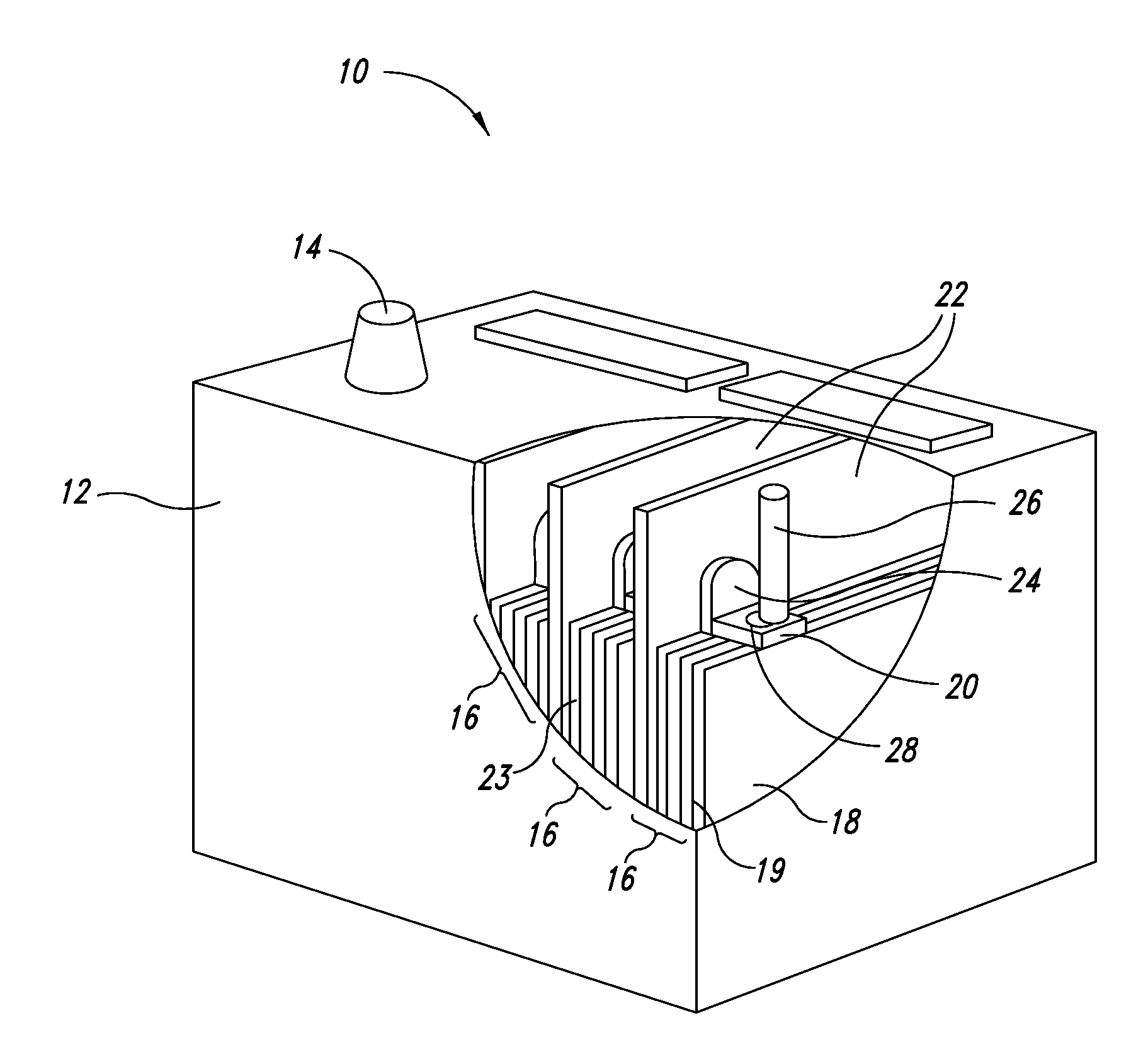
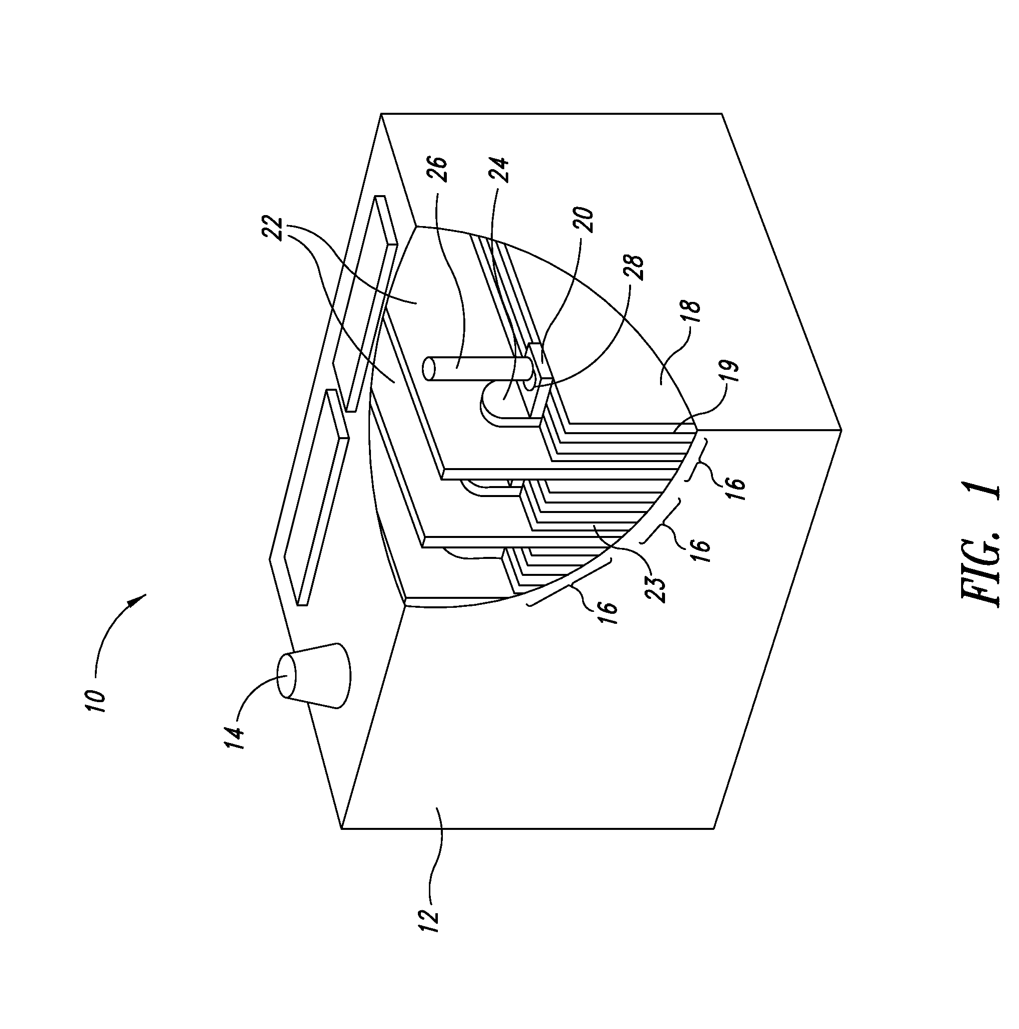
CROSS-REFERENCE TO RELATED APPLICATION[0001]This application claims the benefit under 35 U.S.C. §119(e) of U.S. Provisional Patent Application No. 61 / 493,350 filed Jun. 3, 2011; which application is incorporated herein by reference in its entirety.BACKGROUND[0002]1. Technical Field[0003]The present application relates to compositions and devices for energy storage and distribution. The compositions comprise a plurality of lead particles and a plurality of carbon particles and exhibit desirable electrochemical properties suitable for use in hybrid carbon-lead energy storage devices.[0004]2. Description of the Related Art[0005]Hybrid energy storage devices, also known as asymmetric supercapacitors or hybrid battery / supercapacitors, utilize a combination of battery electrodes and supercapacitor electrodes. For example, hybrid lead-carbon energy storage devices employ lead-acid battery positive electrodes (cathodes) and ultracapacitor negative electrodes (anodes). Such devices comprise ...

Claims


Application Information

Patent Timeline
IPC IPC(8): H01M4/36H01M10/08H01M4/58H01M4/56H01M4/60
CPCH01G11/50H01M4/14H01M4/56H01M4/625Y02E60/13Y02E60/126Y02T10/7022Y02T10/7016H01M10/06H01B1/02H01B1/04H01B1/18Y02E60/10Y02T10/70C08K3/04C08K3/08C08K7/22H01M4/583H01M2004/021
Inventor THOMPKINS, LEAH A.FEAVER, AARON M.COSTANTINO, HENRY R.CHANG, ALAN TZU-YANGGERAMITA, KATHARINESAKSHAUG, AVERY
Owner BASF SE
Why Eureka
Try Eureka