
Medical probe and method of using same

Active Publication Date: 2013-01-03
ST JUDE MEDICAL CARDILOGY DIV INC
View PDF6 Cites 47 Cited by
  • Summary
  • Abstract
  • Description
  • Claims
  • Application Information

AI Technical Summary

Benefits of technology

The present invention provides a device with a probe that can be easily inserted into the esophagus for treating tissue in the area. The probe has a J shape to make the insertion process easier. The device also includes a controller that receives signals from electrodes and temperature sensors on the probe and displays an anatomical map of the esophagus on a video monitor. A thermal map of the esophagus is also displayed and can be overlaid on the anatomical map. The controller can also display the position of the probe relative to the anatomical map. The device can be used in real time and the thermal map is continuously updated. This invention provides a more effective and safe way to treat tissue in the esophagus.

Problems solved by technology

Extensive radiofrequency ablation in this location carries the potential risk of collateral damage to structures adjacent to the left atrial posterior wall, including the esophagus.
An atrial esophageal fistula is a rare, but almost always a lethal complication.
A problem with such known procedures is that there is presently a high rate of esophageal injuries.
The ongoing high rate of esophageal thermal injury, despite luminal esophageal temperature (LET) monitoring, is specifically related to the limitations of current techniques and medical devices used for LET monitoring.
For example, there is often suboptimal orientation and positioning of the LET probe in relationship to the site of radiofrequency application in the heart, which results in an underestimation of the true LET and leads to esophageal injury due to unseen temperature rises.
Current modalities reduce but do not eliminate left atrial-esophageal fistulas.
Esophageal injury is associated with a high mortality rate in addition to numerous co-morbidities.
Fistula formation is thought to occur due to conductive heat transfer to the esophagus that causes trans-mural tissue injury leading to a fistulous connection between the esophageal lumen and the left atrium, leading to sepsis, stroke and eventual death.
Unfortunately, there is no clear method to accurately define the precise location of the esophagus.
Therefore, the esophagus is essentially vulnerable to thermal injury during RF ablation from any location along the posterior left atrial endocardium.
A disadvantage of these known systems and methods is that they do not provide live visualization of the probe itself within the anatomic shell of the esophagus.
Another disadvantage of known systems and methods is that it has not been possible to non-fluoroscopically visualize the location of a temperature sensor within the esophagus relative to the distal end of an intra-cardiac ablation catheter prior to each ablation, limiting the accuracy of the temperature readings.
This problem is compounded because of variability in left atrial and esophageal anatomy, including the esophageal wall thickness.
A disadvantage of this device is that it does not enable the creation of a live, continuously updating electroanatomic or thermal shell of the esophagus.
Another disadvantage of the device disclosed in U.S. Pat. No. 7,819,817 is that it requires a permanent balloon for positioning the probe.
The balloon serves to anchor the esophagus in one location and limits natural esophageal mobility; thus, increasing the potential for esophageal injury to that anchored location.
A further complication from a balloon includes an increased risk for aspiration by obstructing the natural peristalsis of esophageal and pharyngeal secretions, increasing the risk for a severe pneumonia and respiratory failure.
In addition, the balloon can cause great discomfort to the patient both on swallowing and with prolonged inflation during the procedure.
The permanent cable and balloon add increased size and stiffness and increases the risk for trauma to the esophageal lumen.
Unfortunately, studies have shown that despite these imaging modalities being performed within 24 hours of the procedure, there was still significant migration of the esophagus up to 15 mm in less than 24 hours.
Thus, imaging the esophagus prior to the procedure is inadequate to locate the true and precise anatomic location of the esophagus.
Clinical studies have shown that leaving an esophageal echocardiography probe in the esophagus throughout the procedure leads to a higher risk of esophageal-atrial fistulas.
A disadvantage of this device is that it is solely a temperature-sensing device and does not include any electrodes.
In addition, the operator can not visualize this device within the esophagus in real time during the procedure due to the lack of electrodes; thus, precluding live feedback to the operator in regards to the relative distance between the esophageal device and the cardiac ablation catheter.
However, clinical studies have shown that cooling systems are not effective in cooling the deep muscular layers of the esophagus, which are the initial sites of thermal injury in contact with the left atrium and serve as the origin for fistula formation.
Thus, the catheter simply cools the exposed surface area of the esophagus, which is not only ineffective in protecting the esophagus but also causes great discomfort to the patient.
A disadvantage of the type of system is that there is no direct visualization of the esophagus or atrium via an anatomic or thermal map.
Furthermore, proximity is indicated by measured proximity signals, which can be inaccurate secondary to the anatomic variability between the two catheters.
In addition, there can be persistent and latent heating up to sixty seconds after termination of ablation.
A disadvantage of this catheter is that it only provides a static esophageal map.
It does not provide live and continuous temperature readings, nor does it allow for concomitant cardiac pacing or sensing or have the capability to create a live three dimensional and continuously updating esophageal thermal map.

Method used


Image

  • Medical probe and method of using same
  • Medical probe and method of using same
  • Medical probe and method of using same

Examples


Embodiment Construction

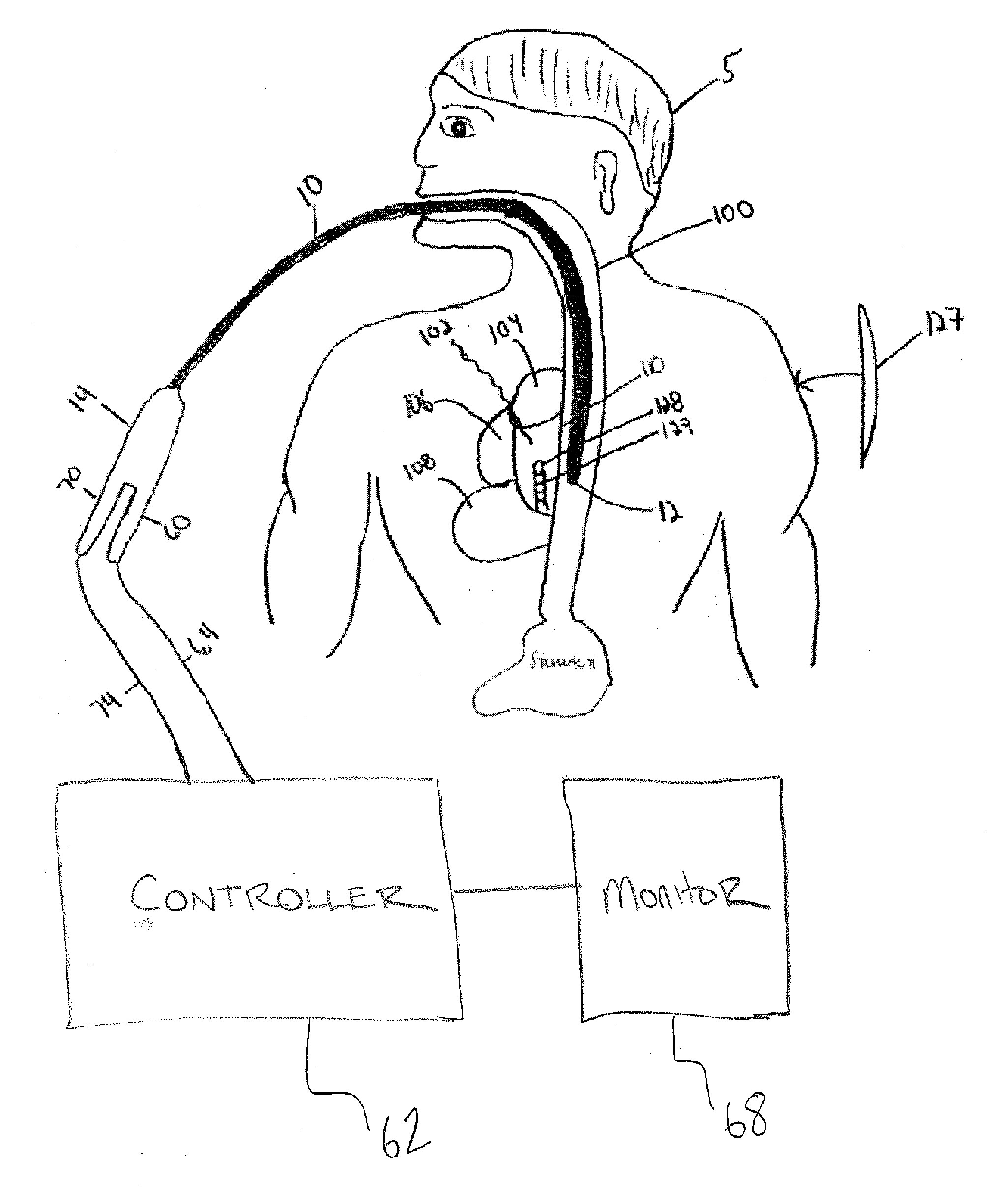
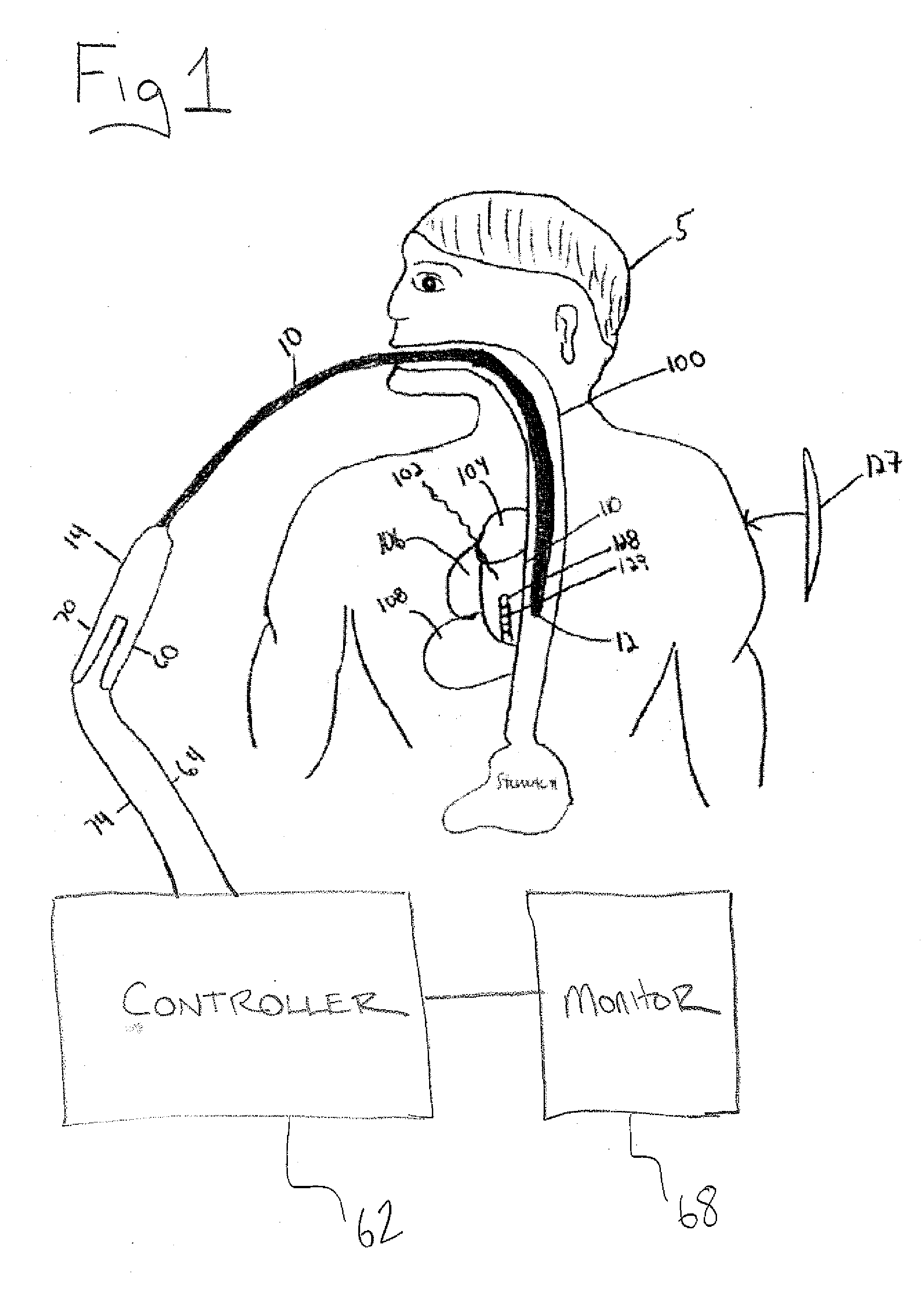
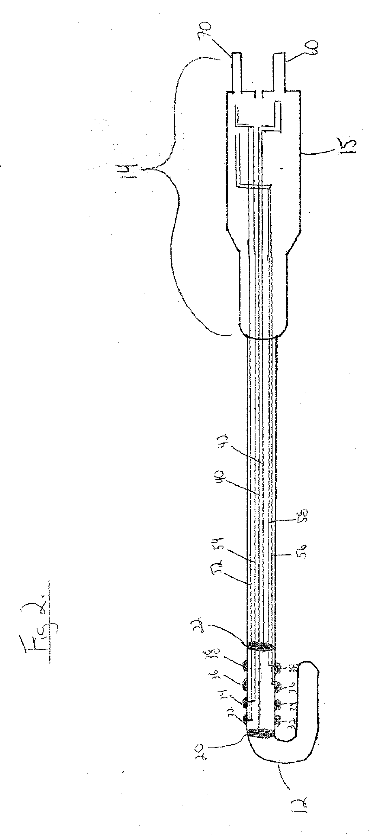
[0042]In general reference to FIGS. 1-9, an esophageal probe 10 in accordance with one embodiment of the present invention is disclosed. It should be noted that although the term probe is used to refer to the medical device disclosed in the present application, it could also be referred to as a catheter or any other term known in the art.

[0043]In reference to FIGS. 1-2, the probe 10 extends along a longitudinal axis between a proximal end 14 and a distal end 12. The probe 10 is adapted so that it can be advanced into a patient's 5 esophagus 100 via oral-pharyngeal or naso-pharyngeal insertion so that the distal end 12 is located proximate to the posterior left cardiac wall 110 and the proximal end 14 is outside the patient's body. The left ventricle 108, the right ventricle 106, the left atrium 102, and the right atrium 104 are shown in FIG. 1. The intra-cardiac catheter 128 with electrodes 129 is also shown in FIG. 1.

[0044]In the embodiments shown, the distal end 12 of the probe is...


PUM


Abstract

The present invention resides in one aspect in a device for monitoring luminal esophageal temperatures in a patient. The device includes a probe adapted to be inserted into an esophagus of the patient. The probe extends between a proximal end and a distal end. A first temperature sensor and a second temperature sensor are coupled to the probe. An electrode is also coupled to the probe. The second temperature sensor is displaced from the first temperature sensor along a longitudinal axis of the probe. A controller processes information received by the electrodes and the temperature sensors. The controller generates a live and continuously updating three dimensional anatomic map and three dimensional thermal map of the esophagus based at least in part on the information received from the temperature sensors and the electrodes. The thermal map and the anatomic map are displayed on a video monitor.

Description

CROSS-REFERENCE TO RELATED APPLICATIONS[0001]The present application claims the benefit under 35 U.S.C. §119(e) of the Provisional Patent Application Ser. No. 61 / 503,743 filed Jul. 1, 2011, the disclosure of which is incorporated herein by reference in its entirety.FIELD OF THE INVENTION[0002]The present invention generally relates to a medical probe and a method of using the same. More specifically, the present invention relates to an esophageal probe having one or more temperature sensors and one or more electrodes disposed proximate to a distal end of the probe. The probe allows for continuous, live, and simultaneous esophageal temperature and location monitoring through three dimensional anatomic mapping and three dimensional thermal mapping during an electrophysiology procedure or a surgical procedure.BACKGROUND OF THE INVENTION[0003]Catheter or electrophysiology ablation is an invasive cardiac procedure that uses radio-frequency (RF) energy or cyroablation to remove faulty ele...

Claims


Application Information

Patent Timeline
IPC IPC(8): A61B5/01
CPCA61B2018/00791A61B2018/00797A61B2018/00821A61B2018/00839A61B2018/00357A61B2018/00642A61B2018/00351A61B5/015A61B2018/00708A61B5/042A61B5/4233A61B5/4848A61B18/1492A61B2018/00666A61B5/283A61B18/1233A61B2018/1467A61B2018/00577
Inventor TIANO, JOSEPH
Owner ST JUDE MEDICAL CARDILOGY DIV INC
Learn More