Wind powered electrical generator-hydraulic-natural gas power augmented

a technology of natural gas and wind power, applied in the direction of wind power, electric generator control, control system, etc., can solve the problems of reducing the service life of critical components, achieving consistent wind velocity and direction, etc., and achieves the effect of reducing cooling requirements, reducing drag or resistance, and efficient application

Inactive Publication Date: 2013-01-10
CORNELIUS STEVEN LOUIS
View PDF2 Cites 13 Cited by
  • Summary
  • Abstract
  • Description
  • Claims
  • Application Information

AI Technical Summary

Benefits of technology

[0025]This approach allows power to be efficiently applied to the main generator shaft as needed and also to freewheel when not in use, eliminating drag or resistance on the main shaft when the hydraulic power / propulsion system (auxiliary engine and hydraulic pump assembly) isn't engaged. Matching the variable-displacement pump operating at the base unit is a similar (variable-displacement) hydraulic motor (propulsion unit) mounted inside the power cab (up top) will have enough inherent control via the swashplate control and return valves to obviate a separate viscous coupling. The swashplate valves would also “freewheel” in the depressurized (0 swashplate angle) mode, reducing cooling requirements. This approach is modeled after the scheme used in the constant-speed generators on aircraft engines. The design weight for the aux / dual power unit is approximately 1000 pounds, though weight can vary depending upon rated horsepower specified / required for individual generator applications. More than 80% of the unit's weight will be in the base unit (engine and hydraulic pump). The auxiliary engine will be located at the base of the main power generation cab of the wind powered electrical generator and supply locomotive force to the main generator shaft via a hydraulic pressure to a viscous planetary (reduction gear) system (FIG. #2, page 31), by way of a ring and pinion gearset commonly used in automotive applications. One other method of supplying torque to turn the mainshaft will be through a scaled hydraulic turbine, connected directly to the mainshaft. The planetary gearing system and a viscous coupling system, very much like the power distribution system on a full-time all-wheel drive set-up employed on some sports utility vehicles, allows the auxiliary engine to engage and maintain generator shaft speed when needed and disengage when wind velocity is sufficient to turn the generator shaft. This approach will save fuel and engine wear when the auxiliary power supply isn't needed to turn the main shaft and generate a constant supply of electricity. Inclusion of the planetary gear system is important to the overall design, because the planetary gear assembly multiplies the torque generated by the hydraulic power unit (power head) by a factor of six to ten (6× to 25×), permitting a much smaller aux power assembly to be used in very broad applications, lowering initial and sustained operating costs.

Problems solved by technology

The uncertainty of achieving consistent wind velocity and direction has been the historical and primary limiting factor inhibiting large-scale adaption of wind power to augment the national electrical grid and provide a reliable and renewable energy source.
Sudden, high-pressure shocks to the various connection joints and propulsion system could cause instantaneous component failure (metal fatigue or shearing) and certainly would reduce the service life of critical components.
The most likely condition causing the auxiliary propulsion system to engage would be insufficient wind velocity (calm days) or gusting velocities that exceed rated rotational speed of the propeller assembly (unpredictable weather / storm conditions), which would fail to turn the main generator shaft at the required RPM to assure specified / rated electrical output.

Method used


Image

  • Wind powered electrical generator-hydraulic-natural gas power augmented
  • Wind powered electrical generator-hydraulic-natural gas power augmented
  • Wind powered electrical generator-hydraulic-natural gas power augmented

Examples


Embodiment Construction

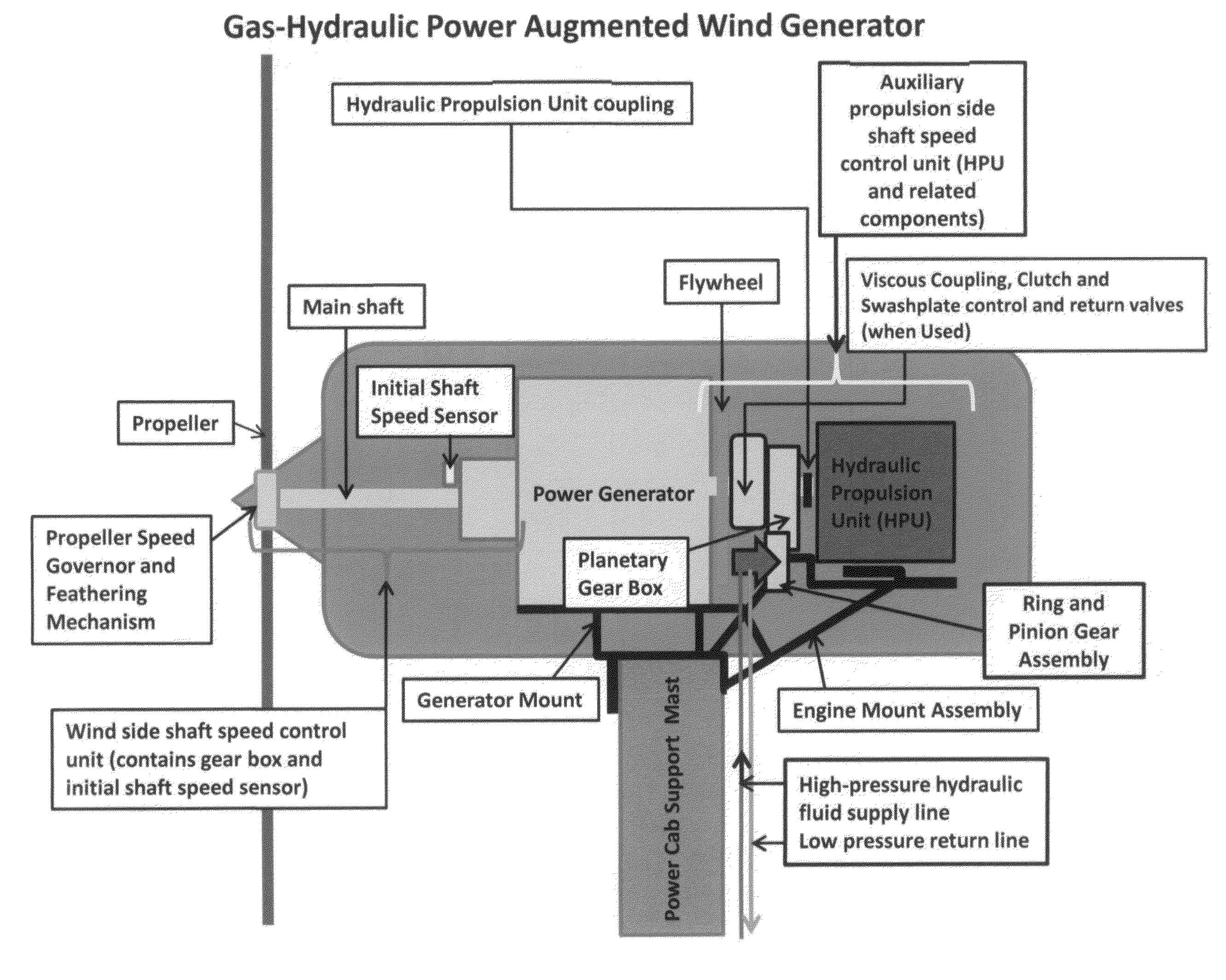
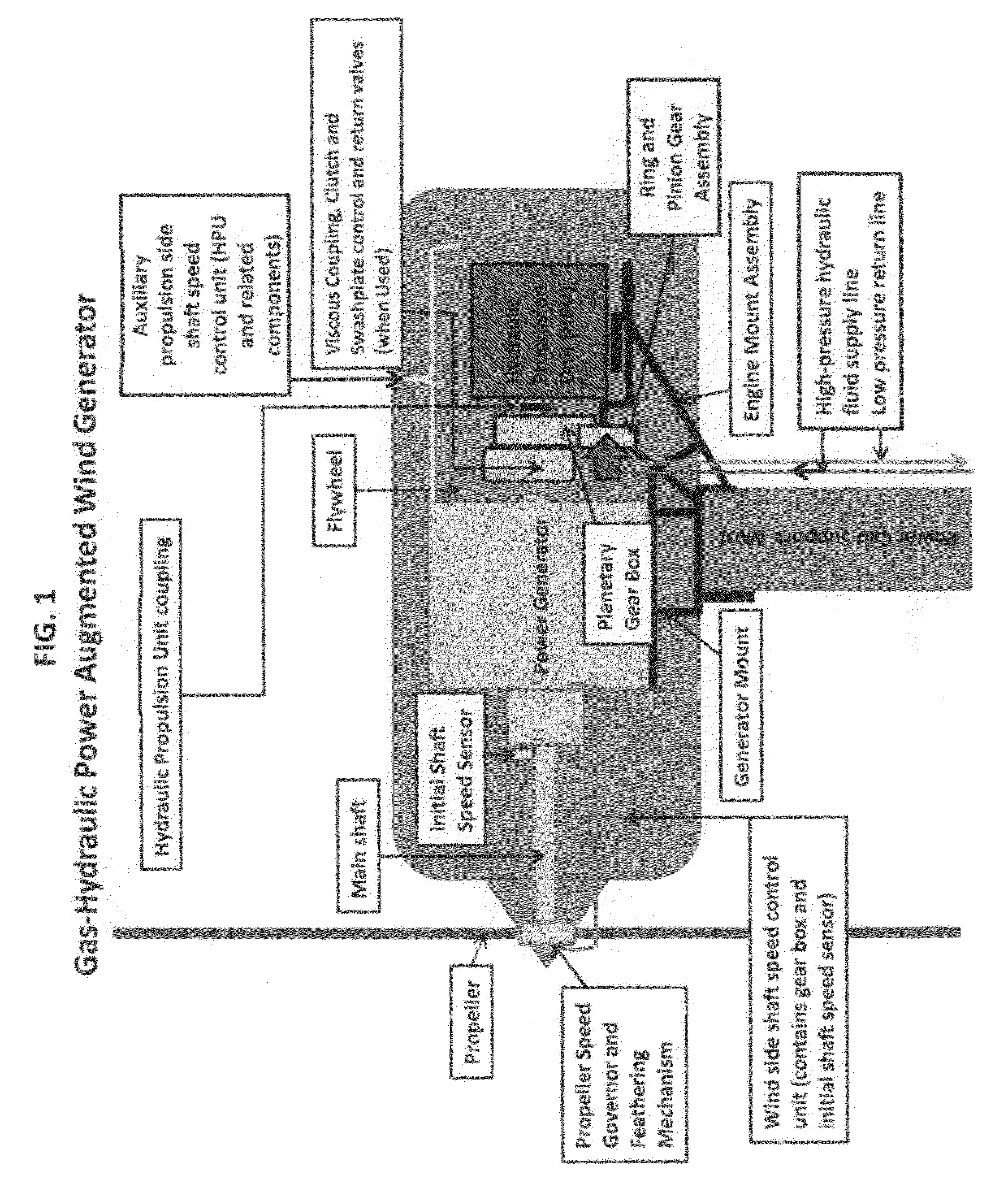
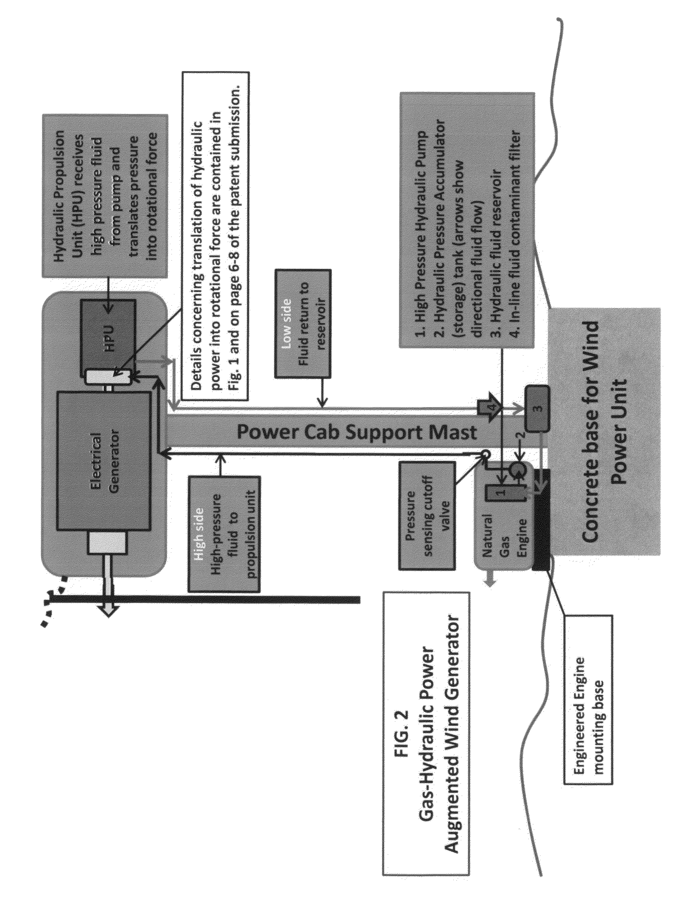
[0054]Design will incorporate an efficient natural gas powered engine, driving a hydraulic power unit mounted behind the power generation assembly (on the aft or non-wind end of the power cab) as an alternate locomotive source to turn the wind-powered electrical generator. The entire auxiliary propulsion system would consist of: 1) a natural gas engine; 2) a high pressure hydraulic pump driven by the natural gas powered engine; 3) a pressure accumulation (storage) tank with associated check and release valves calibrated to the pressure range required to power the propulsion unit; 4) a particulate filter to remove foreign matter from the fluid as it flows through the closed-loop hydraulic system to the reservoir for use by the hydraulic pump; 5) a control panel linked to the sensors mounted on the main generator shaft, and; 6) a hydraulic propulsion system connected to the hydraulic pump via high-pressure lines (hydraulic fluid supply and return). Items 1 through 4 would be mounted a...


PUM


Abstract

Natural gas (NG) fueled auxiliary power source, combined with a high-pressure hydraulic pump supplying hydraulic fluid to a secondary hydraulic propulsion unit mounted (hung) on the rear (aft) of the wind generator main shaft provides axial force (torque) to the mainshaft via a ring and pinion set and planetary gearbox, or scaled turbine propulsion unit equipped with shaft speed sensors that have been calibrated to minimum/maximum desired main shaft (electrical generator) speed and that can engage and spin the main shaft attached to the electrical power generator on demand when there is insufficient wind to do so.

Description

CROSS REFERENCE TO RELATED APPLICATION[0001]NONESTATEMENT REGARDING FEDERALLY SPONSORED RESEARCH OR DEVELOPMENT[0002]No Federal research or development funds were used in the development of this concept / product.THE NAMES OF TILE PARTIES TO A JOINT RESEARCH AGREEMENT[0003]N / AINCORPORATION-BY-REFERENCE OF MATERIAL SUBMITTED ON A COMPACT DISC[0004]N / ABACKGROUND OF THE INVENTION[0005]The current generation of wind powered electrical generators is completely dependent upon a sufficient velocity of wind driving their massive propellers, thereby rotating the main throughput shaft which is connected to an electrical generator, spinning the generator which in turn produces electricity for consumer use. The uncertainty of achieving consistent wind velocity and direction has been the historical and primary limiting factor inhibiting large-scale adaption of wind power to augment the national electrical grid and provide a reliable and renewable energy source.[0006]One proposed solution to provid...

Claims


Application Information

Patent Timeline
Patent Type & Authority Applications(United States)
IPC IPC(8): F03D9/00
CPCY02E10/725F05B2220/50F03D9/002F03D9/00F03D9/25Y02E10/72F03D80/00
Inventor CORNELIUS, STEVEN LOUIS
Owner CORNELIUS STEVEN LOUIS
Why Eureka
Try Eureka