Anisotropic rare earth magnet powder, method for producing the same, and bonded magnet

Active Publication Date: 2013-01-10
AICHI STEEL
View PDF2 Cites 22 Cited by
  • Summary
  • Abstract
  • Description
  • Claims
  • Application Information

AI Technical Summary

Benefits of technology

[0094]When attention is focused on specimen No. 5-5 in which the content of Nd as a rare earth element (Rm=Rt) in the magnet powder produced only with a magnet raw material (or simply a “magnet raw material”) was close to a theoretical composition value of 11.8 at. % which is necessary to generate R2TM14B1-type crystals, coercivity (iHc) was extremely low. Therefore, although having a composition which is supposed to inherently provide a high magnetic flux density (Br), specimen No. 5-5 was affected by the decrease in coercivity and, as a result, had a low magnetic flux density.
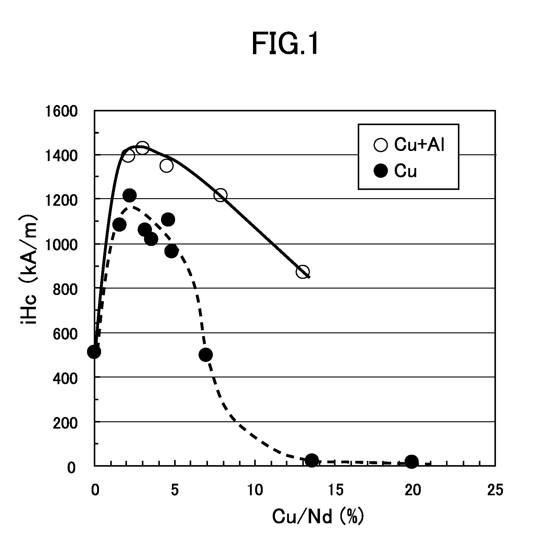
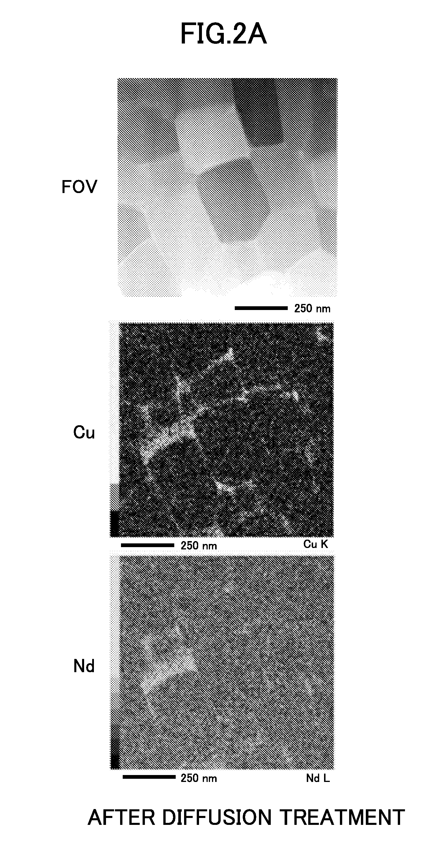
[0095]In contrast, when attention is focused on specimen Nos. 1-1 to 1-6 in which diffusion raw materials comprising, for example, NdCu were respectively diffused into the magnet raw material which had a similar composition to that of specimen No. 5-5 (M1 in Table 1), coercivity sharply increased. This tendency was similarly observed in specimen Nos. 2-1 to 2-4 in which diffusion raw materials comprising NdCuAl were respectively diffused. It is supposed to be because in these specimens which attained a sharp increase in coercivity, enveloping layers (a diffusion layer) comprising NdCu or NdCuAl were formed in grain boundaries of Nd2TM14B1-type crystals by the diffusion treatment. On the other hand, in specimen Nos. 5-1 and 5-3 which contained Cu from the stage of base alloys (ingots) and were not subjected to diffusion treatment, coercivity was remarkably low. Especially when specimen No. 4-1 and specimen No. 5-1 or specimen No. 4-4 and specimen 5-3 are compared with each other, in spite of similar overall composition, specimen Nos. 5-1 and 5-3 containing Cu from the stage of ingots were degraded in magnetic characteristics and were remarkably decreased especially in coercivity than specimen Nos. 4-1 and 4-4 subjected to diffusion treatment.
[0096]These differences are supposed to be caused by a difference in the form of existence of Nd and Cu in the vicinity of R2TM14B1-type crystals. That is to say, even if Nd and Cu are present in the vicinity of R2TM14B1-type crystals in specimen Nos. 5-1 and 5-3 containing Cu from the stage of the ingots, the Nd and Cu are thought to be different in characteristics such as viscosity and wettability from the enveloping layers of the present invention and to have the shape of aggregates and not to envelop surfaces of crystals. In contrast, in specimen Nos. 4-1 and 4-4 subjected to the diffusion treatment, Nd and Cu had optimum composition for viscosity, wettability and so on, and the Nd and Cu are thought to have enveloped surfaces of R2TM14B1-type crystals approximately uniformly or smoothly. As a result, it is estimated that in specimen Nos. 4-1 and 4-4, distortion present on the surfaces of the R2TM14B1-type crystals was corrected or generation of reverse magnetic domains was effectively suppressed in the vicinity of the surfaces, and coercivity which was remarkably higher than those of specimen Nos. 0.5-1 and 5-3 was exhibited.
[0097]Moreover, a com

Problems solved by technology

However, Dy, Ga and the like are very scarce elements and use of these elements has a

Method used


Image

  • Anisotropic rare earth magnet powder, method for producing the same, and bonded magnet
  • Anisotropic rare earth magnet powder, method for producing the same, and bonded magnet
  • Anisotropic rare earth magnet powder, method for producing the same, and bonded magnet

Examples


Example

Example 1

Production of Specimens

(1) Preparation of Magnet Raw Materials

[0084]Various kinds of magnet raw materials comprising magnet alloys having the composition shown in Table 1 were prepared (hereinafter, component composition will be all expressed in at. %. Nd in Table 1 corresponds to Rm.). These magnet raw materials were produced as follows. First, raw materials weighed so as to have the composition shown in Table 1 were melted and magnet alloys (base alloys) casted by strip casting process (hereinafter referred to as “SC process”) were obtained. These magnet alloys were held in an Ar gas atmosphere at 1140 deg. C. for ten hours, thereby homogenizing structure (a homogenization heat treatment step).

[0085]Next, the magnet alloys after subjected to hydrogen decrepitation in a hydrogen atmosphere under a hydrogen pressure of 0.13 MPa were subjected to hydrogenation treatment (d-HDDR), thereby obtaining powdery magnet raw materials. This hydrogenation treatment was conducted as fo...

Example

Example 2

[0113]The following respective specimens were produced in addition to the aforementioned specimens and evaluated in various points.

(1) Specimen No. 6-1

[0114]Specimen No. 6-1 shown in Table 4 comprised a magnet powder obtained by changing the temperature of the high-temperature hydrogenation step from 840 deg. C. to 860 deg. C. Overall composition, magnetic characteristics and so on of the thus obtained specimen are shown in Table 4. As apparent from Table 4, coercivity (iHc) of magnet powder can be further increased to about 1500 to 1650 kA / m by controlling the high-temperature hydrogenation step (the structure stabilization step) and applying the diffusion treatment. Production of the respective specimens was carried out under the same conditions as those of Example 1 (hereinafter referred to as the “standard conditions”), unless otherwise specified. The same applies to the following specimens.

(2) Specimen Nos. 7-1 to 7-13

[0115]Specimen Nos. 7-1 to 7-13 shown in Table 5 re...


PUM

PropertyMeasurementUnit
Lengthaaaaaaaaaa
Fractionaaaaaaaaaa
Percent by atomaaaaaaaaaa

Abstract

The anisotropic rare earth magnet powder of the present invention includes powder particles having R2TM14B1-type crystals of a tetragonal compound of a rare earth element (R), boron (B), and a transition element (TM) having an average crystal grain diameter of 0.05 to 1 μm, and enveloping layers containing at least a rare earth element (R′) and copper (Cu) and enveloping surfaces of the crystals. Owing to the presence of the enveloping layers, coercivity of the anisotropic rare earth magnet powder can be remarkably enhanced without using a scarce element such as Ga and Dy.

Description

TECHNICAL FIELD[0001]The present invention relates to anisotropic rare earth magnet powder having good magnetic characteristics, a method for producing the same, and a bonded magnet.BACKGROUND ART[0002]A bonded magnet comprising a shaped solid body of rare earth magnet powder bonded with a binder resin exhibits very high magnetic characteristics and at the same time has a high degree of freedom in shape and the like. Therefore, such bonded magnets are expected to be used in various kinds of devices, such as electric appliances and automobiles which are desired to achieve energy saving and weight reduction.[0003]However, in order to increase the use of the bonded magnets, the bonded magnets are needed to exhibit stable magnetic characteristics even in a high-temperature environment. Therefore, earnest research and development is carried out to improve coercivity of bonded magnets or rare earth magnet powders these days.[0004]The present research and development is just at such a leve...

Claims


Application Information

Patent Timeline
IPC IPC(8): H01F1/09H01F7/02B22F1/06B22F1/17
CPCB22F1/025C22C33/0278C22C38/005C22C38/06H01F1/0578H01F7/0221H01F41/0293H01F1/0572C22C38/16B22F1/06B22F1/17C22C38/002C22C38/12B22F9/023B22F9/04B22F2301/355B22F2998/10H01F7/02
Inventor HONKURA, YOSHINOBUMISHIMA, CHISATOYAMAZAKI, MASAO
Owner AICHI STEEL
Why Eureka
Try Eureka