Integrated photovoltaic cell and radio-frequency antenna

a photovoltaic cell and radio frequency technology, applied in the direction of antennas, photovoltaic energy generation, radiating elements structural forms, etc., can solve the problems of increasing the cost and size of the wireless module, surpassing the cost of the electronic integrated circuit, and achieving the effect of maximum solar or low cos

Active Publication Date: 2013-01-10
DANESH MINA
View PDF5 Cites 74 Cited by
  • Summary
  • Abstract
  • Description
  • Claims
  • Application Information

AI Technical Summary

Benefits of technology

[0063]A further advantage of one of the integrated photovoltaic cell and RF antenna assemblies disclosed is that its thickness may be very small, in the nanometer or the micrometer range in one embodiment.
[0064]Another advantage of one of the integrated photovoltaic cell and RF antenna assemblies disclosed is that it may provide a lightweight system.
[0065]A further advantage of one of the integrated photovoltaic cell and RF antenna assemblies disclosed is that it may be used for a fixed, mobile, portable, or wearable system.
[0066]A further advantage of one of the integrated photovoltaic cell and RF antenna assemblies disclosed is that it may enable a maximization of solar or light radiation absorption with three-dimensional, rotating photovoltaic cell elemen

Problems solved by technology

Some wireless systems use smart antenna technology, such as MIMO (multiple-input multiple-output), where antenna diversity is achieved by using two or more antennas for higher spectral efficiency and link reliability, which adds to the cost and size.
Nowadays, the antenna and packaging of the wireless system have become the bottleneck of the system by increasing to one-third of the cost of the wireless module, far surpassing the cost of the electronic integrated circuits.
Unfortunately, prior art photovoltaic cell, or “solar antenna”, and radio-frequency antennas solutions presented do not offer the flexibility and the compactness required for low-power transceiver systems, such as for autonomous wireless sensor netwo

Method used


Image

  • Integrated photovoltaic cell and radio-frequency antenna
  • Integrated photovoltaic cell and radio-frequency antenna
  • Integrated photovoltaic cell and radio-frequency antenna

Examples


Embodiment Construction

[0086]In the following description of the embodiments, references to the accompanying drawings are by way of illustration of an example by which the invention may be practiced. It will be understood that other embodiments may be made without departing from the scope of the invention disclosed.

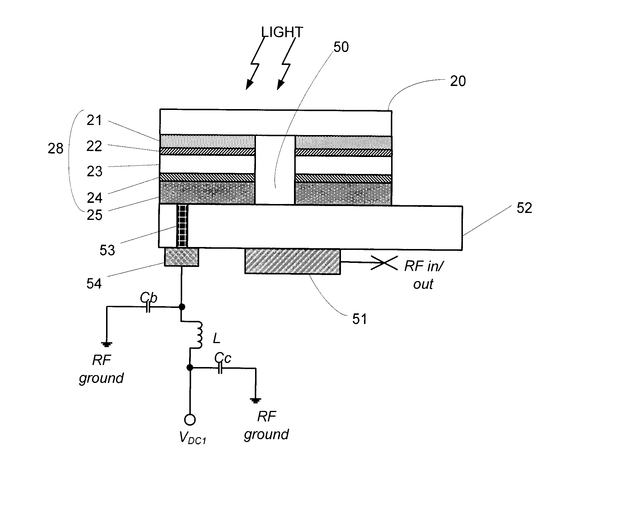
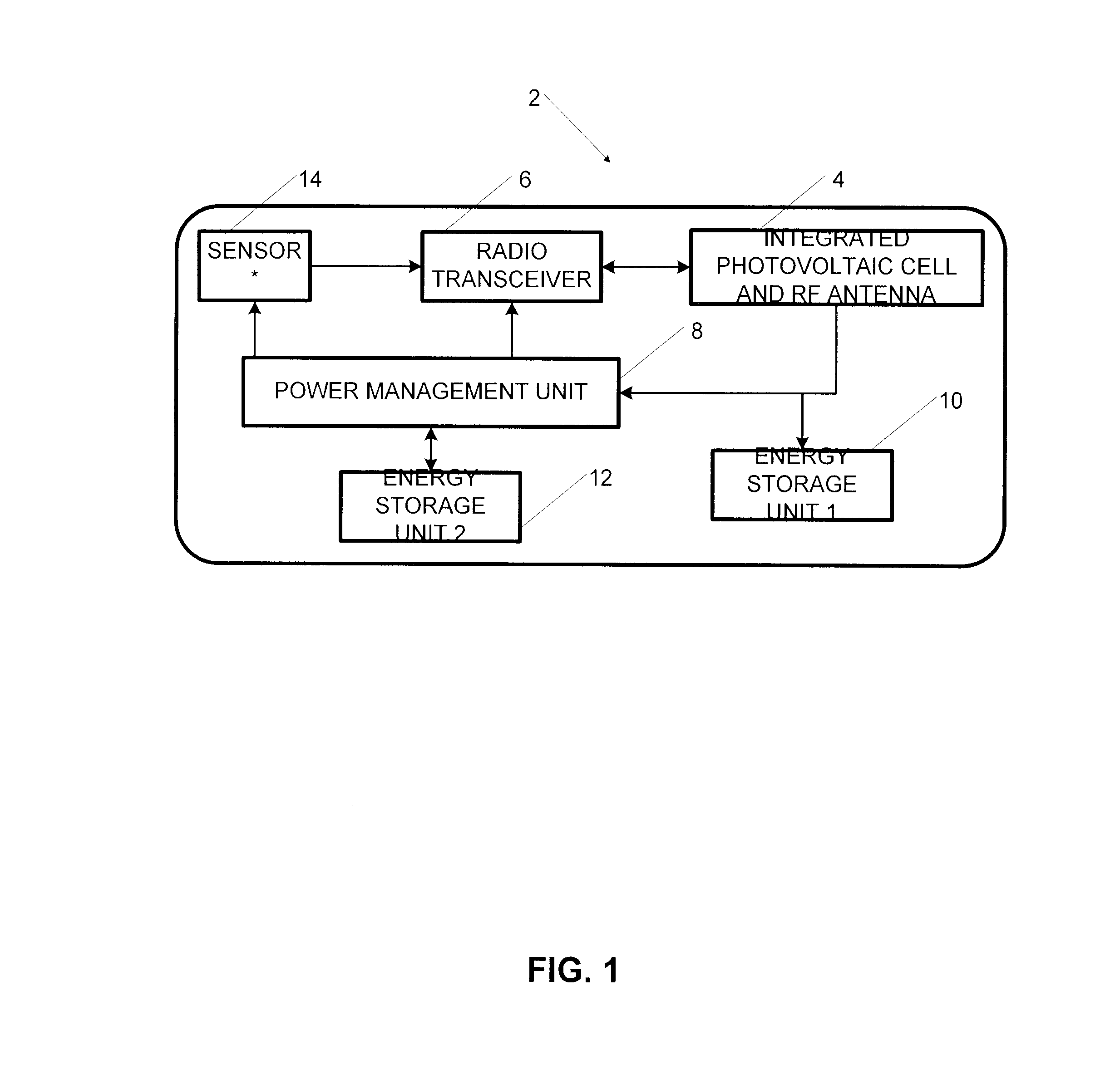
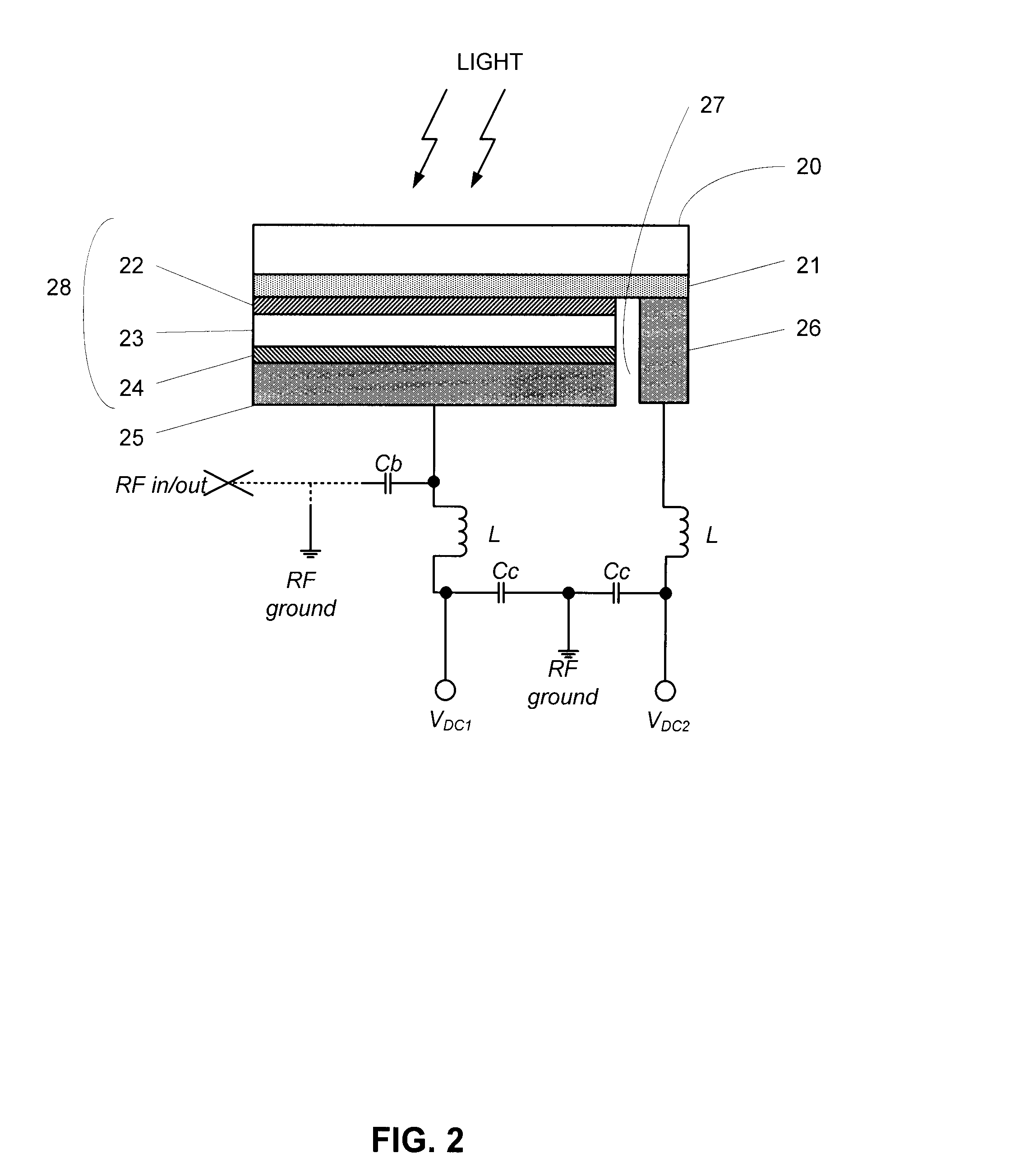
[0087]A wireless autonomous transceiver 2 using light or solar energy harvesting is shown in FIG. 1. The wireless autonomous transceiver 2 comprises an integrated photovoltaic cell and radio-frequency (RF) antenna assembly 4, a radio transceiver 6, a power management unit 8, a first optional energy storage 10, a second optional energy storage 12 and an optional sensor 14.

[0088]The integrated photovoltaic cell and RF antenna assembly 4 acts as an RF antenna and as a DC energy generator and interfaces with the radio transceiver 6, the power management unit 8, and optionally the energy storage unit 10 or several energy storage units 10, 12. In the case of wireless sensor network (WSN) applications...


PUM


Abstract

An integrated photovoltaic cell and RF antenna assembly is disclosed, the assembly comprising a photovoltaic cell and at least two horizontal portions of conductive material, each of the at least two horizontal portions of conductive material being secured under the photovoltaic cell, wherein two of the at least two horizontal portions are used for providing an electrical potential difference and the RF antenna is provided using the photovoltaic cell and at least one of the at least two horizontal portions of conductive material.

Description

CROSS-REFERENCE TO RELATED APPLICATIONS[0001]The application claims priority of U.S. Patent Application No. 61 / 316,919, entitled “Integrated Photovoltaic Cell and Radio-Frequency Antenna” that was filed on Mar. 24, 2010, the specification of which is hereby incorporated by reference.FIELD OF THE INVENTION[0002]The invention relates to electronics components. More precisely, this invention pertains to an integrated photovoltaic (PV) cell and radio-frequency (RF) antenna assembly for the conversion of photon energy into DC electrical energy and for radiating and / or receiving electromagnetic waves.BACKGROUND[0003]Light or solar energy harvesting is needed for autonomous wireless transceivers which are compact in size, have a low cost, are light weight, and may be mobile. Moreover, portable, wearable, or other wireless devices may have non-linear shapes and may be flexible. Antennas other than wires are generally manufactured on a rigid or flexible printed circuit board or material, usi...

Claims


Application Information

Patent Timeline
IPC IPC(8): H01Q1/46
CPCY02E10/50H01G9/20H01Q1/44H01L31/04H01L31/022425H01L31/075Y02E10/548H01Q1/38H01Q13/18H01Q9/04
Inventor DANESH, MINA
Owner DANESH MINA
Why Eureka
Try Eureka