White LED lamp, backlight, light emitting device, display device and illumination device

a technology of led lamps and backlights, applied in the field can solve the problems of abnormal chromaticity, low light output, and damage to illuminated objects, and achieve the effects of reducing the amount of uv light in the released light and heat generation of white led lamps, excellent energy efficiency and energy-saving performance, and reducing the effect of uv ligh

Active Publication Date: 2013-01-10
SEOUL SEMICONDUCTOR
View PDF12 Cites 23 Cited by
  • Summary
  • Abstract
  • Description
  • Claims
  • Application Information

AI Technical Summary

Benefits of technology

[0038]Furthermore, according to the illumination device of this invention, the amount of UV light contained in the released light and the amount of heat generated from the white LED lamp are small. Therefore, an amount of harmful ultra violet rays leaked from the white LED lamp is small, and a harmful effect against eyes and skin can be excluded. In addition, an amount of heat generated from the illumination device is small, so that the illumination device is excellent in energy efficiency and energy-saving performance (energy conservation property).

Problems solved by technology

However, according to the conventional white LED lamp of Type 3, when a part of UV light emitted from the light emitting diode chip is not converted into a visible light and the non-converted UV light is released to outside the LED lamp, an affect of UV light and an affect of heat generated from the white LED lamp act to each other whereby there has been posed problems of causing the following phenomena.
Namely, in a case where the white LED lamp of Type 3 is used as a light source of backlight for a liquid display device, there arises problems such that resin-made peripheral members such as a light guide plate or optical film or the like of the crystal liquid display device are changed into yellow (yellow discoloration) whereby the luminance of the crystal liquid display device is disadvantageously lowered, and an abnormal chromaticity occurs.
Further, in a case where the white LED lamp of Type 3 is used as a light source of an illumination device, there arises problems such that the illuminated object is damaged and a discoloration would occurs.
Therefore, the conventional white LED lamp of Type 3 cannot be used as a light source of the illumination device provided to a picture gallery and art museum.

Method used


Image

  • White LED lamp, backlight, light emitting device, display device and illumination device
  • White LED lamp, backlight, light emitting device, display device and illumination device
  • White LED lamp, backlight, light emitting device, display device and illumination device

Examples


first embodiment

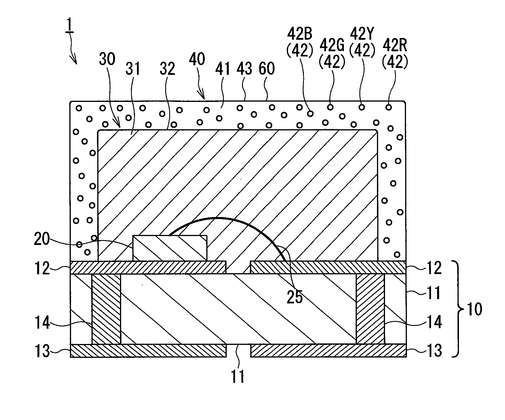
[0052]FIG. 1 is a cross sectional view schematically showing a first embodiment of a white LED lamp according to the present invention. As shown in FIG. 1, the white LED lamp1 comprises: a substrate 10 provided with a front surface side electrode 12 as a conductive portion which is provided on an insulation portion 11; a light emitting diode chip mounted on the front surface side electrode 12 of the substrate 10; a transparent resin layer 30 for sealing the light emitting diode chip 20; and a phosphor layer 40 for covering the transparent resin layer 30.

[0053](Substrate)

[0054]The substrate 10 comprises: the insulation portion 11; the front surface side electrode 12 provided to the front side of the substrate 10 and a rear surface side electrode 13 provided to a rear surface side of the substrate 10; and a power-supplying via 14 passing through the insulation portion 11 so as to establish an electrical connection between the front surface side electrode 12 and the rear surface side e...

second embodiment

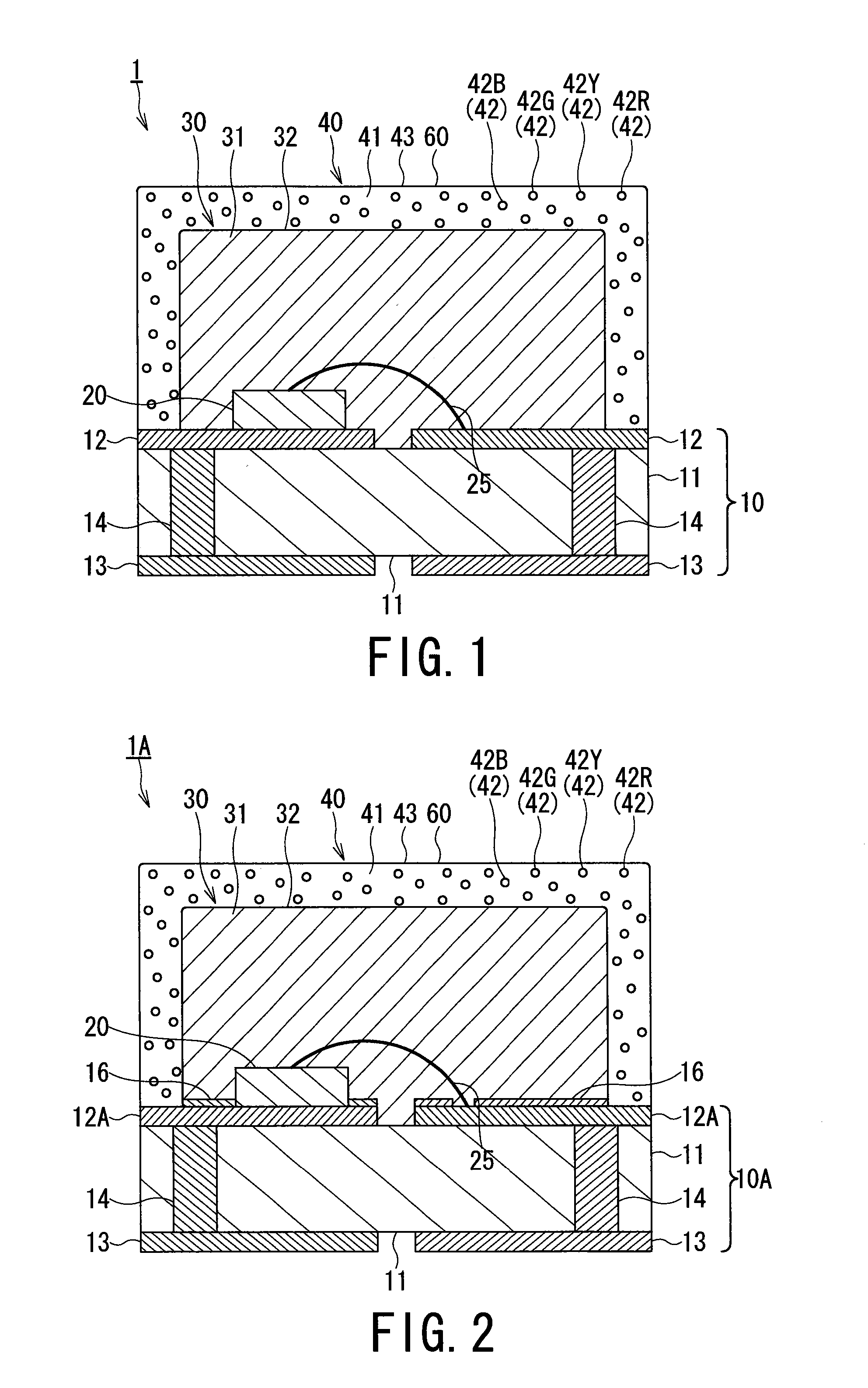
[0137]FIG. 2 is a cross sectional view schematically showing a structure of a second embodiment of the white LED lamp according to the present invention. The white LED lamp 1A of the second embodiment shown in FIG. 2 is configured by using a substrate 10A in place of the substrate 10 used in the white LED lamp 1 of the first embodiment shown in FIG. 1. Other elements of the white LED lamp 1A according to the second embodiments shown in FIG. 2 are the same as those of the white LED lamp 1 according to the first embodiments shown in FIG. 1. Therefore, the same reference numerals are used to denote the same members or elements as those of the first embodiment, and the detailed explanations of these members or elements are simplified or omitted hereunder.

[0138]In this second embodiment, the substrate 10A is used in place of the substrate 10, the front surface side electrode 12A is used in place of the front surface side electrode 12, and a light reflecting layer 16 is further formed to ...

third embodiment

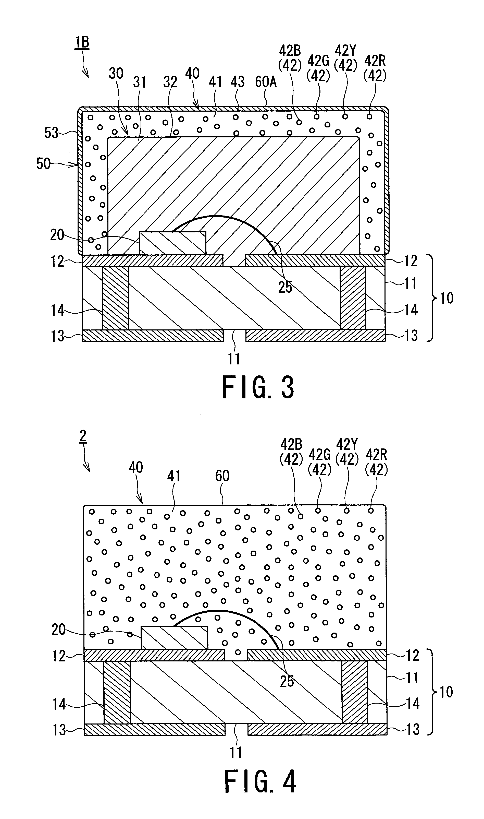
[0156]FIG. 3 is a cross sectional view schematically showing a structure of a third embodiment of the white LED lamp according to the present invention. With respect to the white LED lamp 1 of the first embodiment, the white LED lamp 1B of the third embodiment shown in FIG. 3 is configured to further form a UV absorbing layer 50 onto the surface of the phosphor layer 40.

Other elements of the white LED lamp 1B according to the third embodiments shown in FIG. 3 are the same as those of the white LED lamp 1 of the first embodiments shown in FIG. 1. Therefore, the same reference numerals are used to denote the same members or elements as those of the first embodiment, and the detailed explanations of these members or elements are simplified or omitted hereunder.

[0157]The UV light absorbing layer 50 is formed by dispersing UV light absorbing powder into a third transparent resin hardened substance (not shown).

[0158]The third transparent resin hardened substance is a product prepared by h...


PUM


Abstract

A white LED lamp including: a conductive portion; a light emitting diode chip mounted on the conductive portion, for emitting a primary light having a peak wavelength of 360 nm to 420 nm; a transparent resin layer including a first hardened transparent resin, for sealing the light emitting diode chip; and a phosphor layer covering the transparent resin layer, the phosphor layer being formed by dispersing a phosphor powder into a second hardened transparent resin, and the phosphor powder receiving the primary light and radiating a secondary light having a wavelength longer than that of the primary light. An energy of the primary light contained in the radiated secondary light is 0.4 mW / Im or less.

Description

CROSS-REFERENCE TO RELATED APPLICATION[0001]This application is a continuation application of U.S. application Ser. No. 12 / 919,287, filed Aug. 25, 2010, the entire contents of which are incorporated herein by reference, which is a National Stage application of PCT / JP09 / 052,863 filed on Feb. 19, 2009, and claims priority to Japanese Patent Application Nos. P2008-043344, filed on Feb. 25, 2008; P2008-304117 filed Nov. 28, 2008; and P2008-307611 filed Dec. 2, 2008.TECHNICAL FIELD[0002]The present invention relates to a technical lighting device comprising: a light emitting diode for emitting UV light (ultraviolet light) to purple light as a primary light from the light emitting diode; and a phosphor layer for receiving the UV light to purple light and emitting a white light; wherein the phosphor layer is composed of transparent resin and phosphor powder dispersed in the transparent resin, and the phosphor powder receives the UV light to purple light and emits a secondary light having a...

Claims


Application Information

Patent Timeline
Patent Type & Authority Applications(United States)
IPC IPC(8): H01L33/50G09F13/04
CPCC09K11/584C09K11/642H01L33/642H01L33/54H01L33/505H01L33/405C09K11/7734C09K11/7739C09K11/7741C09K11/7789H01L33/44H01L33/504H01L33/507H01L33/60H05B33/14H05B33/20Y02B20/181H01L2224/48091H01L2224/48465H01L33/32H01L2924/00014H01L2924/00Y02B20/00C09K11/77342C09K11/77348
Inventor ISHII, TSUTOMUTAKEUCHI, HAJIMEOOYA, YASUMASANAKAGAWA, KATSUTOSHIITO, YUMITOYOSHIMA, MASAKISHIRAKAWA, YASUHIROSAKAI, RYO
Owner SEOUL SEMICONDUCTOR
Why Eureka
Try Eureka