For example, error-free communications might be possible if there were no bandwidth, latency or power-consumption constraints on a
communication channel and
system, but in most applications there are some constraints that require some design for robustness.
However, where some computation is needed to
encode and decode the information, the time needed for that computation is added to the latency.
As is well-known, a processor and memory can perform arbitrarily complex operations (e.g., table lookups, Fast Fourier transformations, multiplications, arbitrary finite algebra, etc.) that cannot be performed by two or three logic gates, but some designs are so power-consumption and latency limited that the design only allows for a few logic gates.
For example, if the
communication channel is between two parts of a
chip or between two chips, it might not be practical to insert a processor and
instruction memory between those two parts, consuming
chip or board real estate as well as power, in order to effect some particular communications scheme.
As an example, network communications between two
microwave relay stations might be made reliable by using transmission powers of multiple watts, multiple levels of convolutional coding,
handshaking for acknowledgements and
retransmission of lost packets, and the like, where the power needed to perform the computations is largely irrelevant relative to the power needed to send the
signal over the medium, but none of that would be practical for communications between two chips on a circuit board or between two circuits on a
chip where the power needed to perform any needed computational, circuit or
logical operations would be much larger than what is needed to actual convey the signals.
To send more robust signals, the amplitude of the signals can be increased, but that might lead to increased
noise in other parts of the channel or system, in addition to increased
power consumption.
While distinct wires may carry distinct signals, it is often the case that signals on one wire will induce undesirable signals on another wire, either by
signal-to-
signal noise,
common mode noise or other known phenomenon.
In most chip-to-chip communication systems, the error performance has to be very low (e.g., less than one error in 1012 bits) and a certain amount of energy is required to achieve the error performance.
There are several reasons why it is difficult to design high speed, low power,
small footprint and low error-rate chip-to-chip communication systems.
First, communication is not perfect and the signals transmitted on the wires are disturbed by
noise and interference.
In chip-to-chip communications some sources of noise are thermal noise, common-mode noise and interference,
crosstalk,
reference noise and switching noise.
An important type of switching noise is simultaneous switching output (“SSO”) noise.
For others, such as SSO noise and
crosstalk, increasing the transmit power is not beneficial since these noise types tend to increase as well.
A second impairment of chip-to-chip communications is that the physical medium tends to attenuate the signals transmitted on the wires.
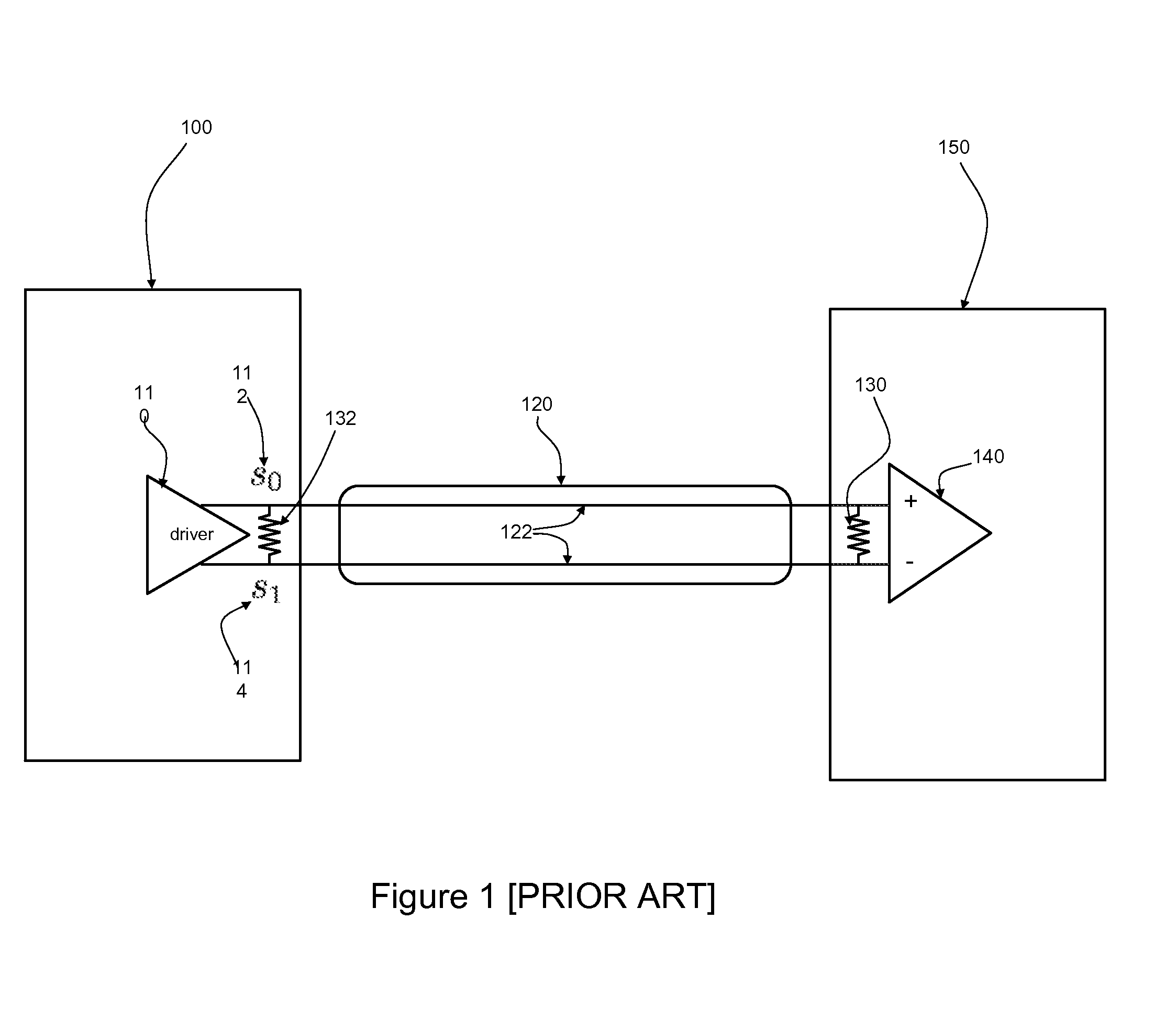
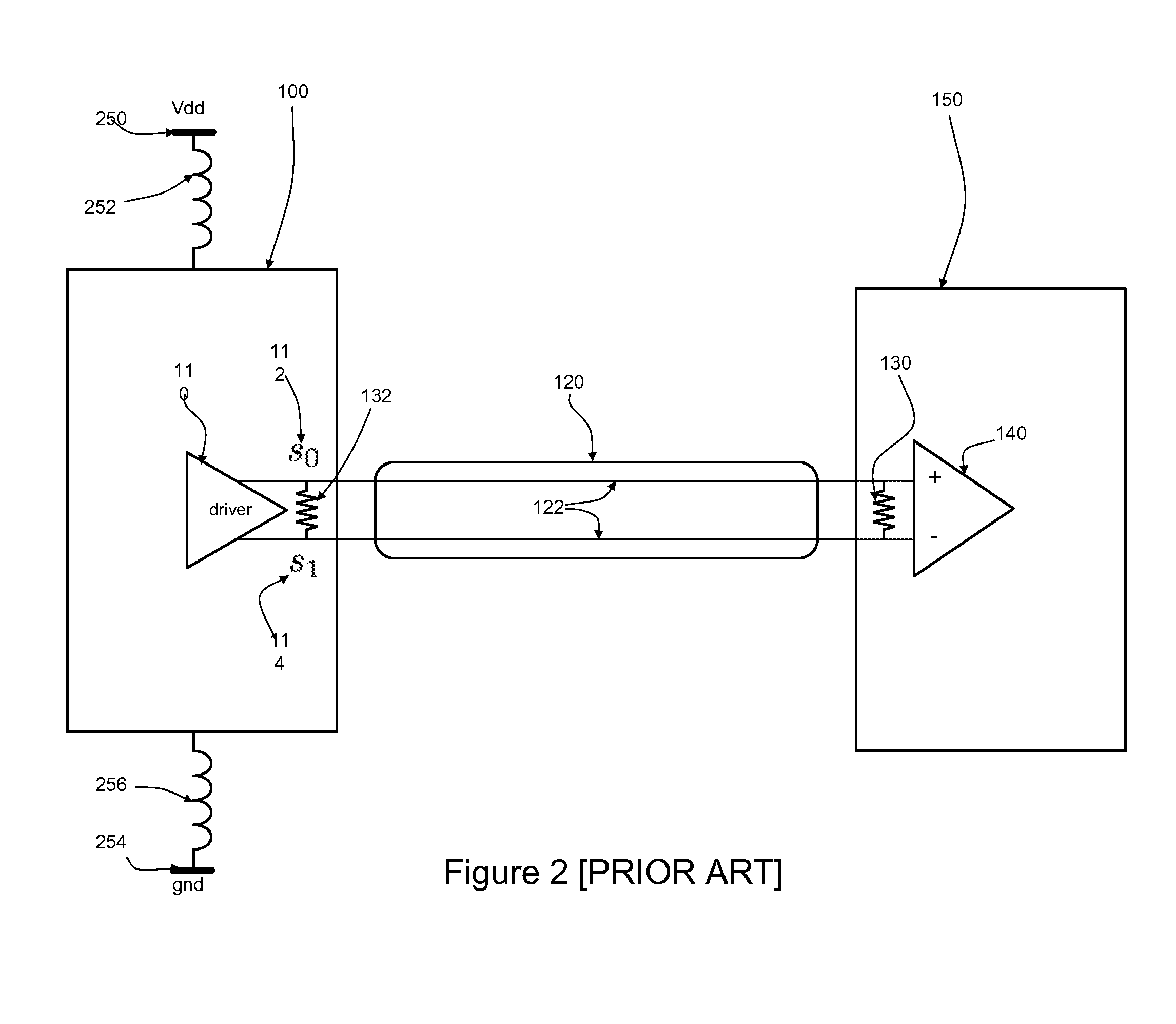
The scheme disclosed in [Poulton] retains several of the noise resilience properties of
differential signaling, but creates other problems.
Also, as pointed out in [Poulton], the method disclosed there is not very power-efficient.
Finally, encoding and decoding the signaling method as disclosed in [Poulton] is not straightforward, especially when the number of wires is more than four and therefore much power might be consumed in just the
processing and handling of signaling.
There are several problems to this approach.
This is only possible for a small number of
bus wires such that the total required current can be limited.
Second, encoding and decoding such signaling schemes is only possible for a small number of
bus wires to avoid overly complex encoding and decoding.
Third, introducing memory between consecutive bus cycles increases the
delay of the bus communication system.
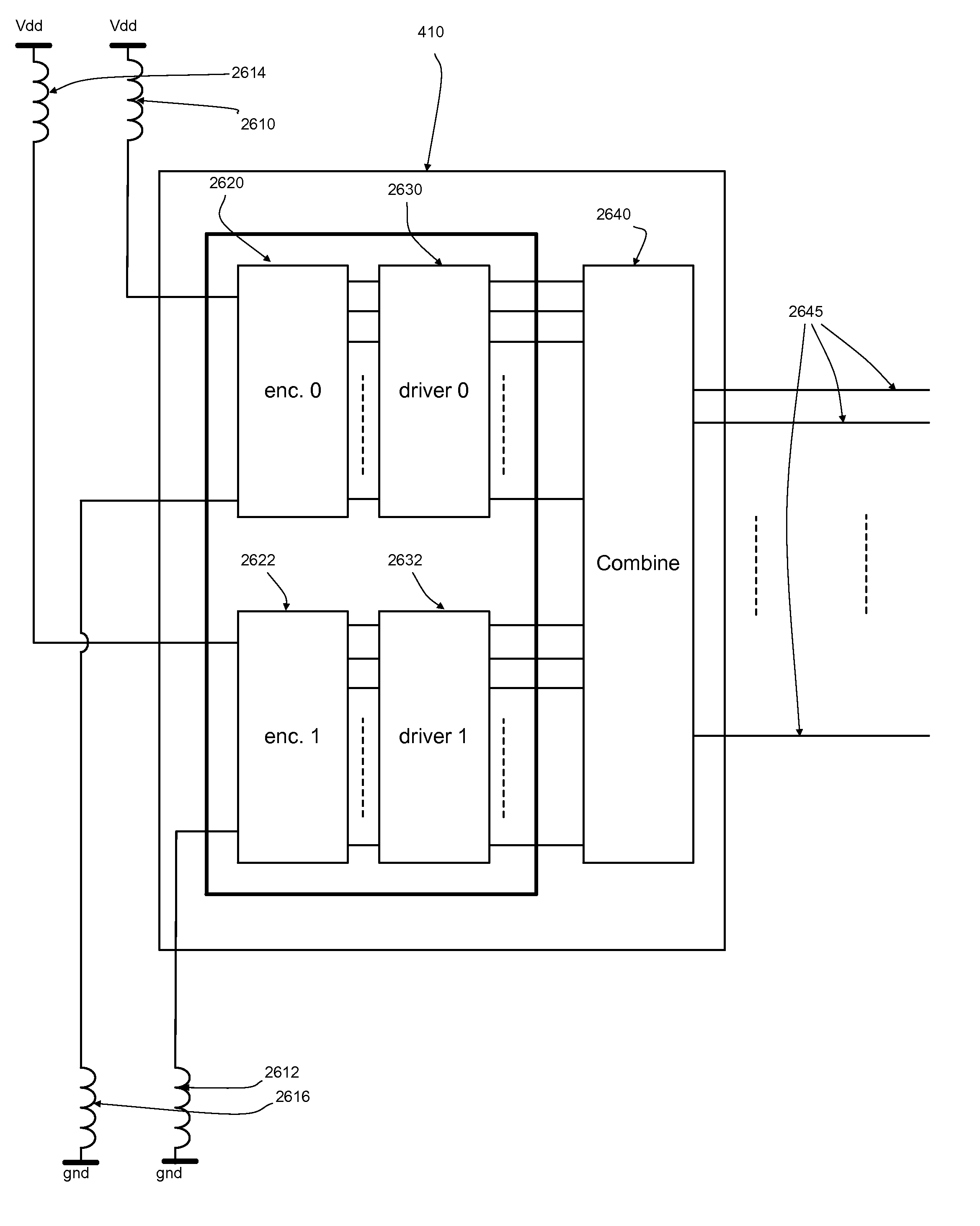
These codes lead to pin-efficient and noise resilient chip-to-chip communications, while keeping the
power consumption of
transmitter and
receiver low compared to conventional signaling methods.

