Rolling bearing

Active Publication Date: 2013-01-17
NTN CORP
10 Cites 6 Cited by

AI-Extracted Technical Summary

Problems solved by technology

Thus the DLC film has disadvantages that it is low in its adhesiveness to a base material and liable to peel therefrom.
But when the supply of the fluorine grease to a rolling contact portion and a sliding portion is short, and thereby boundary lubrication may occur.
As a result, a reaction takes place between perfluoropolyether (hereinafter referred to as PFPE) oil which is the base oil fluorine grease and steel (iron) which is a material of ...

Method used

[0054]A residual stress occurs in the hard film such as the DLC film. The magnitude of the residual stress varies independence on a film structure, a film-forming condition, and a base material configuration. As a result of repeated experiments, it has been revealed that unexpectedly the residual stress is greatly affected by the configuration of the base material. For example, when a hard film is formed on a flat surface of the base material, it does not peel therefrom and has a large critical peeling load in a scratch test, whereas when it is formed on a curved surface such as raceway of inner and outer rings of a rolling bearing and a pocket surface of a cage thereof, it may peel therefrom immediately after it is formed thereon. Even though the hard film does not peel off the curved surface immediately after it is formed thereon, the hard film may be liable to peel therefrom while the rolling bearing is in operation. As a result of earnest studies, the present inventors have found that by limiting the structure of the hard film to be formed on the curved surface such as the raceway of the inner and outer rings of the rolling bearing, rolling contact surfaces of rolling elements thereof, and the sliding contact surface (pocket surface and the like) of the cage thereof to a predetermined structure composed of a foundation layer (Cr), a mixed layer (layer in which the compositions of WC and DLC are gradient), and a surface layer (DLC), it is possible to greatly improve the peeling resistance of the hard film and prevent the hard film from peeling off the curved surface in a condition in which the bearing is in use. The present invention has been made based on this finding.
[0062]As the iron-based material constructing the inner ring 2, the outer ring 3, and the rolling elements 4 on which the hard film 8 is to be formed, it is possible to use an arbitrary steel stock generally used as a material of the bearing members. For example, high carbon chromium bearing steel, carbon steel, tool steel, martensitic stainless steel are listed. It is preferable that the hardness of the curved surface of each of these bearing members (inner ring 2, outer ring 3, and rolling elements 4) on which the hard film is to be formed is not less than 650 in Vickers hardness Hv. By setting the hardness of the curved surface of each of the bearing members to not less than 650 in Vickers hardness Hv, it is possible to decrease the difference between the hardness of the curved surface of each of the bearing members and that of the hard film (foundation layer) and improve the adhesiveness therebetween.
[0064]As the iron-based material constructing the cage 5 on which the hard film 8 is to be formed, it is possible to use an arbitrary material generally used as a material of the cage. For example, a cold-rolled steel plate, carbon steel, chromium steel, chromium molybdenum steel, nickel chromium molybdenum steel, and austenitic stainless steel are listed. The hardness of the sliding contact surface (curved surface) of the cage 5 on which the hard film 8 is to be formed is favorably not less than 190 and more favorably not less than 450 in the Vickers hardness Hv. By setting the Vickers hardness Hv of the sliding contact surface to not less than 450, it is possible to decrease the difference between the hardness of the sliding contact surface and that of the hard film (foundation layer) to a possible highest extent and improve the adhesiveness therebetween.
[0066]It is preferable to form a nitrided layer on the curved surface of the base material of each of the bearing members on which the hard film 8 is to be formed by performing nitriding treatment before the hard film 8 is formed thereon. As the nitriding treatment, it is preferable to subject the surface of the base material to the plasma nitriding treatment because the plasma nitriding treatment makes it difficult for an oxidized layer which prevents the adhesiveness between the hard film and the curved surface of each of the bearing members to be formed. It is preferable that the hardness of the curved surface (surface) of the base material each of the bearing members subjected to the nitriding treatment is not less than 1000 in the Vickers hardness Hv to further improve the adhesiveness between the hard film (foundation layer) and the curved surface of the base material of each of the bearing members.
[0068]Because the foundation layer 8a is composed mainly of the Cr, the foundation layer 8a is compatible with the bearing member made of the iron-based material forming the base material thereof. Thus the foundation layer 8a composed mainly of the Cr is superior to foundation layers composed of W, Ti or Si in the adhesiveness to the base material of the bearing member. The foundation layer 8a is particularly excellent in the adhesiveness to the high carbon chromium bearing steel to be used as a material of the bearing ring of the bearing.
[0070]Because the mixed layer 8b has the gradient composition in which the content rate of the WC becomes lower and that of the DLC becomes higher toward the side of the surface layer 8c, the mixed layer 8b has an excellent adhesiveness to the upper surface of the foundation layer 8a and the lower surface of the surface layer 8c. The mixed layer has a structure in which the WC and the DLC are physically connected to each other and the content rate of the DLC becomes higher toward the side of the surface layer 8c. Therefore the adhesiveness between the surface layer 8c and the mixed layer 8b is excellent.
[0071]The surface layer 8c is composed mainly of the DLC. It is preferable that the surface layer 8c has a gradient layer part 8d, disposed at the side adjacent to the mixed layer 8b, whose hardness becomes higher continuously or stepwise from the side of the mixed layer 8b. When the bias voltage at the mixed layer 8b and that at the surface layer 8c are different from each other, to avoid a sudden change of the bias voltage, a bias voltage is changed (increased) continuously or stepwise. Thereby the gradient layer part 8d is obtained. The change in the bias voltage allows the hard...

Benefits of technology

[0036]In the rolling bearing of the present invention, the hard film having the predetermined membrane structure containing the DLC is formed on the curved surface of the bearing member consisting of the iron-based material. The foundation layer, consisting of the Cr, which is directly formed on the curved surfaces is compatible with the iron-based material and superior to W and Si in its adhesiveness. The WC to be used for the mixed layer has a hardness and a modulus of elasticity intermediate between those of the Cr and the DLC, and the concentration of a stress little occurs after the hard film is formed. By allowing the mixed layer composed of the WC and the DLC to have the gradient composition, the mixed layer has a structure in which the WC and the DLC are physically connected to each other.
[0037]Owing to the above-described structure, the hard film formed on the curved surfaces such as the r...

Abstract

The present invention provides a rolling bearing in which the peeling resistances of a DLC film formed on raceway of inner and outer rings and a sliding surface of a cage are improved to allow the intrinsic properties of the DLC film to be displayed so that the rolling bearing is excellent in its resistance to seizing, wear, and corrosion. A rolling bearing (1) has an inner ring (2), an outer ring (3), a plurality of rolling elements (4), and a cage (5). A hard film (8) is formed on a curved surface such as a raceway (2a) of the inner ring (2), a raceway (3a) of the outer ring (3), and the like. The hard film (8) is composed of a foundation layer, composed mainly of Cr, which is formed directly on the curved surface, a mixed layer, composed mainly of WC and DLC, which is formed on the foundation layer, and a surface layer, composed mainly of the DLC, which is formed on the mixed layer. In the mixed layer, the content rate of the WC becomes lower continuously or stepwise in a direction from the side of the foundation layer toward the side of the surface layer, and the content rate of the DLC becomes higher in the above-described direction.

Application Domain

ShaftsVacuum evaporation coating +6

Technology Topic

CorrosionEngineering +3

Image

  • Rolling bearing
  • Rolling bearing
  • Rolling bearing

Examples

  • Experimental program(1)

Example

Example 2-10
[0169]After base material (Vickers hardness Hv: 1000) subjected to the plasma nitrogen treatment by using the radical nitriding apparatus produced by Japan Electronics Industry Co., Ltd was ultrasonically cleaned with acetone, the base material was dried. After the base material was dried, it was mounted on the UBMS/AIP composite apparatus to form the foundation layer (Cr) and the mixed layer (WC/DLC) both made of the materials shown in table 4 in the above-described film-forming condition. The DLC film was formed on the mixed layer which was the surface layer in the film-forming conditions shown in table 4. Thereby a specimen having the hard film was obtained. The obtained specimen was subjected to a test similar to the test conducted in the example 2-1. Results are shown in table 4.
[0170]Hard films were formed on the sliding contact surface (pocket surfaces) of a cage of a 6204 rolling bearing (deep groove ball bearing) shown below in conditions of the examples, the comparative examples, the reference examples. Whether the hard films peeled off the cage immediately after the hard films were formed on the sliding contact surface of the cage was checked. Specimens in which the hard films did not peel off the cage when they were taken out of the film-forming chamber were recorded as “∘”, whereas specimens in which the hard films peeled off the cage when they were taken out of the film-forming chamber were recorded as “x”. Tables show the results.
[0171]Cage: cages each consisting of two separate iron plates (hard film was formed on sliding contact surface of each cage on which rolling elements slide. A base material (material, hardness, surface roughness) of each cage is as shown in table 1).
[0172]By using the cages on which the hard films were formed in the above-described film-forming test, the 6204 rolling bearings (deep groove ball bearing) for the test were assembled. A life length test was conducted on the test bearings by using a testing machine shown in FIG. 11. As shown in FIG. 11, the testing machine is so constructed that a shaft to be rotated by a pulley 72 is supported by a test bearing 71 with a load being applied to the shaft from a load-applying coil spring 73. The reference numeral 74 denotes a cartridge heater, and the reference numeral 75 denotes a thermocouple. The test conditions are shown below.
[0173]Cage: cages each consisting of two separate iron plates (hard film was formed on sliding contact surface of each cage on which rolling elements slide. A. base material (material, hardness, surface roughness) of each cage is as shown in tables)
[0174]Test bearing: 6204 (rubber seal)
[0175]Lubrication: lithium ester-based grease (viscosity of base oil at 40° C.: 26 mm2/second, worked penetration: 260)
[0176]Packed amount: 15% (volume ratio to entire space)
[0177]Load: radial load: 67N, axial load: 67N
[0178]Number of rotations: 10000 r/minute (rotation of inner ring)
[0179]Temperature: 150° C.
[0180]When seizing has occurred on the cage, the cage has reached the end of its life. When the cage has reached the end of its life, the torque rises rapidly. In this test, a period of time (hour) until before the testing machine stops owing to an overload is set as the life length. Tables show the results.
TABLE 4 Example 2-1 2-2 2-3 2-4 2-5 2-6 Base material SPCC SPCC SPCC SPCC SPCC SUS304 Hardness Hv of base material 190 190 190 190 190 200 Surface roughness μmRa of base material 0.24 0.24 0.24 0.24 0.24 0.31 Whether surface treatment was made — — — — — — (“◯”: treated, “—”: not treated) Hardness Hv of nitrided layer — — — — — — Material of foundation layer Cr Cr Cr Cr Cr Cr Material1)(used in combination with DLC) of WC WC WC WC WC WC mixed layer Whether gradient portion2) was formed ◯ ◯ ◯ ◯ ◯ ◯ (“◯”: formed, “—”: not formed) Film-forming condition of surface layer Introduction ratio of methane gas3) 3.0 1.0 5.0 1.5 1.0 3.0 Vacuum degree (Pa) 0.25 0.25 0.25 0.45 0.80 0.25 Bias voltage (negative) applied to base 100 100 100 150 100 100 material (V) Specific wear amount (×10−10 mm3/(N/m)) 100 80 145 135 120 100 Indentation hardness Average value (GPa) 29.5 36.4 26.4 27.7 26.1 27.0 Standard deviation (GPa) 5.2 6.3 4.9 3.4 3.0 3.5 Average value + standard deviation (GPa) 34.7 42.7 31.3 31.1 29.1 30.5 Critical peeling load (N) 68 68 69 69 67 30 Film thickness (μm) 1.4 1.2 1.4 1.2 1.2 1.4 Ratio4) of thickness of surface layer to 0.70 0.70 0.74 0.70 0.70 0.70 that of hard film Test of 6204 bearing Film-formed state of cage ◯ ◯ ◯ ◯ ◯ ◯ Life length before seizing (average value 288 281 240 242 300 290 N = 5) occurred, hour Example 2-7 2-8 2-9 2-10 2-11 Base material SPCC SCM420 SPCC SPCC SPCC Hardness Hv of base material 540 750 190 540 190 Surface roughness μmRa of base material 0.18 0.21 0.45 0.18 0.24 Whether surface treatment was made — — — ◯ — (“◯”: treated, “—”: not treated) Hardness Hv of nitrided layer — — — 1000 — Material of foundation layer Cr Cr Cr Cr Cr Material1)(used in combination with DLC) of WC WC WC WC WC mixed layer Whether gradient portion2) was formed ◯ ◯ ◯ ◯ ◯ (“◯”: formed, “—”: not formed) Film-forming condition of surface layer Introduction ratio of methane gas3) 3.0 3.0 3.0 3.0 3.0 Vacuum degree (Pa) 0.25 0.25 0.25 0.25 0.25 Bias voltage (negative) applied to base 100 100 100 100 100 material (V) Specific wear amount (×10−10 mm3/(N/m)) 100 100 100 100 135 Indentation hardness Average value (GPa) 29.7 29.5 28.5 29.8 26.4 Standard deviation (GPa) 5.0 5.3 4.5 5.1 2.0 Average value + standard deviation (GPa) 34.7 34.8 33.0 34.9 28.4 Critical peeling load (N) 70 68 60 70 65 Film thickness (μm) 1.4 1.4 1.4 1.4 2.8 Ratio4) of thickness of surface layer to 0.70 0.70 0.70 0.70 0.70 that of hard film Test of 6204 bearing Film-formed state of cage ◯ ◯ ◯ ◯ ◯ Life length before seizing (average value 306 360 241 372 490 N = 5) occurred, hour 1)mixed layer in which DLC was used in combination. In the case “WC”, mixed layer consisted of WC/DLC. “—” means that mixed layer was not formed. 2)DLC gradient part in surface layer. 3)“—” means that only Ar gas was used. Introduction ratio of methane gas shows ratio of introduction amount of methane gas to 100 which was introduction amount of Ar gas. 4)Film thickness of surface layer with respect to entire film thickness
TABLE 5 Comparative example 2-1 2-2 2-3 2-4 2-5 2-6 2-7 Base material SPCC CAC301 SPCC SPCC SPCC SUS304 SPCC Hardness Hv of base material 190 160 190 190 190 190 190 Surface roughness μmRa of base material 0.24 0.38 0.24 0.24 0.24 0.24 0.24 Whether surface treatment was made — — — — — — — (“◯”: treated, “—”: not treated) Hardness Hv of nitrided layer — — — — — — — Material of foundation layer — Cr — Cr W Ti Cr Material1)(used in combination with DLC) of — WC WC — WC WC Cr mixed layer Whether gradient portion2) was formed — ◯ ◯ ◯ ◯ ◯ ◯ (“◯”: formed, “—”: not formed) Film-forming condition of surface layer Introduction ratio of methane gas3) — 3.0 3.0 3.0 3.0 3.0 3.0 Vacuum degree (Pa) — 0.25 0.25 0.25 0.25 0.25 0.25 Bias voltage (negative) applied to base — 100 100 100 100 100 100 material (V) Specific wear amount (×10−10 mm3/(N/m)) — 100 100 5) 100 100 120 Indentation hardness Average value (GPa) — 27.0 29.1 29.9 29.0 29.4 29.0 Standard deviation (GPa) — 3.5 5.0 4.5 5.5 4.9 5.1 Average value + standard deviation (GPa) — 30.5 34.1 34.4 34.5 34.3 34.1 Critical peeling load (N) — 30 65 28 60 63 65 Film thickness (μm) — 1.4 2.1 1.8 2.6 2.2 2.9 Ratio4) of thickness of surface layer to — 0.70 0.72 0.78 0.70 0.71 0.72 that of hard film Test of 6204 bearing Film-formed state of cage — X X X X X ◯ Life length before seizing (average value 150 — — — — — 192 N = 5) occurred, hour 5) Because peeling occurred during test, specific wear amount was unmeasurable.
TABLE 6 Reference example 2-1 2-2 2-3 2-4 2-5 2-6 2-7 Base material SPCC SPCC SPCC SPCC SPCC SPCC SPCC Hardness Hv of base material 190 190 190 190 190 190 190 Surface roughness μmRa of base material 0.91 0.24 0.24 0.24 0.24 0.24 0.24 Whether surface treatment was made — — — — — — — (“◯”: treated, “—”: not treated) Hardness Hv of nitrided layer — — — — — — — Material of foundation layer Cr Cr Cr Cr Cr Cr Cr Material1)(used in combination with DLC) of WC WC WC WC WC WC WC mixed layer Whether gradient portion2) was formed ◯ ◯ ◯ ◯ ◯ ◯ ◯ (“◯”: formed, “—”: not formed) Film-forming condition of surface layer Introduction ratio of methane gas3) 3.0 — 10.0 3.0 3.0 3.0 3.0 Vacuum degree (Pa) 0.25 0.80 0.50 0.14 1.05 0.25 0.25 Bias voltage (negative) applied to base 100 100 100 100 100 50 200 material (V) Specific wear amount (×10−10 mm3/(N/m)) 100 250 300 6) 220 250 80 Indentation hardness Average value (GPa) 26.8 19.0 22.0 6) 16.0 20.0 35.0 Standard deviation (GPa) 7.9 2.0 1.5 6) 1.0 3.0 2.0 Average value + standard deviation (GPa) 34.7 21.0 23.5 6) 17.0 23.0 37.0 Critical peeling load (N) 60 60 69 6) 66 65 55 Film thickness (μm) 2.1 2.8 2.4 6) 1.5 2.4 1.2 Ratio4) of thickness of surface layer to 0.70 0.71 0.74 6) 0.71 0.71 0.71 that of hard film Test of 6204 bearing Film-formed state of cage ◯ ◯ ◯ 6) ◯ ◯ ◯ 6) Because discharge did not occur, film could not be formed.
[0181]As shown in table 4, the hard film of each example is excellent in its wear resistance and adhesiveness to the cage and thus peeling of the hard film therefrom could be prevented when the bearing was operated.
[Formation of Film on Inner and Outer Rings and Cage (Influence of Fluorine Grease is included)]
[0182]As the hard film to be formed on the rolling bearing of present invention, hard films were formed on predetermined base materials respectively to evaluate the properties thereof. In addition, similar hard films were formed on inner and outer rings of rolling bearings and the pocket surfaces of cages thereof to evaluate the properties of the rolling bearings.
[0183]Base materials used to evaluate the hard films are those of “inner and outer rings” shown in the tables. The dimensions of the base materials, the DBMS apparatus, the sputtering gas, and the film-forming condition of the foundation layer and that of the mixed layer are the same as those used in the case of the above-described “formation of film on inner and outer rings”.
Examples 3-1 through 3-9, 3-11, 3-12, Comparative Examples 3-2 through 3-6, and Reference Examples 3-1 through 3-8
[0184]After the base materials of the inner and outer rings shown in tables 7 through 9 were ultrasonically cleaned with acetone, the base materials were dried. After the base materials were dried, they were mounted on the UBMS/AIP composite apparatus to form the foundation layer and the mixed layer both made of the materials shown in tables 7 through 9 in the above-described film-forming condition. The DLC film was formed on each mixed layer which was the surface layer in the film-forming conditions shown in tables 7 through 9. Thereby specimens each having a hard film were obtained. “Vacuum degree” shown in each table means a vacuum degree inside the film-forming chamber of the above-described apparatus. The obtained specimens were subjected to the wear test, the hardness test, the film thickness test, and the scratch test similar to those conducted in the case of the above-described “formation of film on inner and outer rings” conducted. Results are shown in the tables. The reference numerals 1) through 6) shown below table 7 apply to tables 8 and 9.
Example 3-10
[0185]After a base material (Vickers hardness Hv: 1000) subjected to the plasma nitrogen treatment by using the radical nitriding apparatus produced by Japan Electronics Industry Co., Ltd was ultrasonically cleaned with acetone, the base material was dried. After the base material was dried, it was mounted on the UBMS/AIP composite apparatus to form the foundation layer (Cr) and the mixed layer (WC/DLC) both made of the materials shown in table 7 in the above-described film-forming condition. The DLC film was formed on the mixed layer which was the surface layer in the film-forming conditions shown in table 7. Thereby specimen having the hard film was obtained. The obtained specimen was subjected to the test similar to that of the example 3-1. Results are shown in table 7.
[0186]Hard films were formed on portions, (inner ring, outer ring, and pocket surface of cage (cage consisting of two separate iron plates)) of the 6204 rolling bearings (deep groove ball bearings) shown in tables, on which the hard films were to be formed in the conditions of the examples, the comparative examples, and the reference examples. Whether the hard films peeled off the above-described portions immediately after they were formed thereon was checked. In each of the examples, the comparative examples, and the reference examples, the film-forming conditions of the inner ring, the outer ring, and the cage are the same except film-forming condition of the base material. In each of the inner ring, the outer ring, and the cage, specimens in which the hard films did not peel off the portions on which the hard films were formed when they were taken out of the film-forming chamber were recorded as “∘”, whereas specimens in which the hard films peeled off any one of inner ring, the outer ring, and the cage when the hard films were taken out of the film-forming chamber were recorded as “x”. Tables show the results.
[0187]The inner and outer rings and the cage in which the hard film could be favorably formed on the portions, shown in tables, where the hard films were to be formed in the film formation test were incorporated in each of test 6204 rolling bearings (deep groove ball bearings). Fluorine grease was packed in each test rolling bearing. A life length test was conducted on the test bearings by using the testing machine shown in FIG. 11. A similar test was conducted on the specimen of the comparative example 3-1 in which the hard film was not formed. Test conditions are shown below.
[0188]Inner ring/outer ring/cage: as shown in tables.
[0189]Test bearing: 6204 (rubber seal)
[0190]Lubrication: fluorine grease (NOXLUB KF1920 produced by NOK Cluver Inc.)
[0191]Packed amount: 5% (volume ratio to entire space)
[0192]Load: radial load: 67N, axial load: 67N
[0193]Number of rotations: 10000 r/minute (rotation of inner ring)
[0194]Temperature: 200° C.
[0195]When seizing has occurred on the cage, the cage has reached the end of its life. When the cage has reached the end of its life, the torque rises rapidly. In this test, a period of time (hour) until before the testing machine stops owing to an overload is set as the life length. Tables show the results.
TABLE 7 Example 3-1 3-2 3-3 3-4 3-5 3-6 Film-formed portion1) inner, inner, inner, inner, inner, inner, outer, C outer, C outer, C outer, C outer, C outer, C Inner and outer rings Material SUS440C SUS440C SUS440C SUS440C SUS440C SUJ2 Hardness (Hv) 650 650 650 650 650 780 Surface roughness (μmRa) 0.005 0.005 0.005 0.005 0.005 0.005 Whether surface treatment was made — — — — — — (“◯”: treated, “—”: not treated) Hardness of nitrided layer (Hv) — — — — — — Cage Material SUS304 SUS304 SUS304 SUS304 SUS304 SPCC Hardness (Hv) 200 200 200 200 200 190 Surface roughness (μmRa) 0.31 0.31 0.31 0.31 0.31 0.24 Whether surface treatment was made — — — — — — (“◯”: treated, “—”: not treated) Hardness of nitrided layer (Hv) — — — — — — Material of foundation layer2) Cr Cr Cr Cr Cr Cr Material of mixed layer3) WC WC WC WC WC WC Whether gradient portion4) was formed (“◯”: ◯ ◯ ◯ ◯ ◯ ◯ formed, “—”: not formed) Film-forming condition of surface layer Introduction ratio5) of methane gas 3.0 1.0 5.0 1.5 1.0 3.0 Vacuum degree (Pa) 0.25 0.25 0.25 0.45 0.80 0.25 Bias voltage (negative) (V) 100 100 100 150 100 100 Specific wear amount (×10−10 mm3/(N/m)) 100 80 145 135 120 100 Indentation hardness Average value (GPa) 29.5 36.4 26.4 27.7 26.1 27.0 Standard deviation (GPa) 5.2 6.3 4.9 3.4 3.0 3.5 Average value + standard deviation (GPa) 34.7 42.7 31.3 31.1 29.1 30.5 Critical peeling load (N) 68 68 69 69 67 30 Film thickness (μm) 1.4 1.2 1.4 1.2 1.2 1.4 Ratio6) of thickness of surface layer to 0.70 0.70 0.74 0.70 0.70 0.70 that of hard film Test of 6204 bearing Film-formed state of cage ◯ ◯ ◯ ◯ ◯ ◯ Life length before seizing (average value not less not less not less not less not less not less N = 2) occurred, hour than 500 than 500 than 500 than 500 than 500 than 500 Example 3-7 3-8 3-9 3-10 3-11 3-12 Film-formed portion1) inner, inner, inner, inner, inner, inner, outer, C outer, C outer, C outer, C outer, C outer Inner and outer rings Material S53C SUJ2 SUJ2 SUS440C SUS440C SUS440C Hardness (Hv) 650 780 780 650 650 650 Surface roughness (μmRa) 0.005 0.005 0.045 0.005 0.005 0.005 Whether surface treatment was made — — — ◯ — — (“◯”: treated, “—”: not treated) Hardness of nitrided layer (Hv) — — — 1000 — — Cage Material SPCC SCM420 SPCC SUS304 SPCC CAC301 Hardness (Hv) 540 750 190 200 190 160 Surface roughness (μmRa) 0.18 0.21 0.45 0.31 0.24 0.38 Whether surface treatment was made — — — ◯ — — (“◯”: treated, “—”: not treated) Hardness of nitrided layer (Hv) — — — 1000 — — Material of foundation layer2) Cr Cr Cr Cr Cr Cr Material of mixed layer3) WC WC WC WC WC WC Whether gradient portion4) was formed (“◯”: ◯ ◯ ◯ ◯ ◯ ◯ formed, “—”: not formed) Film-forming condition of surface layer Introduction ratio5) of methane gas 3.0 3.0 3.0 3.0 3.0 3.0 Vacuum degree (Pa) 0.25 0.25 0.25 0.25 0.25 0.25 Bias voltage (negative) (V) 100 100 100 100 100 100 Specific wear amount (×10−10 mm3/(N/m)) 100 100 100 100 135 100 Indentation hardness Average value (GPa) 29.7 29.5 28.5 29.8 26.4 28.8 Standard deviation (GPa) 5.0 5.3 4.5 5.1 2.0 4.9 Average value + standard deviation (GPa) 34.7 34.8 33.0 34.9 28.4 33.7 Critical peeling load (N) 70 68 60 70 65 69 Film thickness (μm) 1.4 1.4 1.4 1.4 2.8 1.5 Ratio6) of thickness of surface layer to 0.70 0.70 0.70 0.70 0.70 0.70 that of hard film Test of 6204 bearing Film-formed state of cage ◯ ◯ ◯ ◯ ◯ ◯ Life length before seizing (average value not less not less not less not less not less not less N = 2) occurred, hour than 500 than 500 than 500 than 500 than 500 than 500 1)Inner ring is shown by “inner”. Outer ring is shown by “outer”. Cage is shown by “C”. 2)Layer corresponding to Cr layer. “—” shows that foundation layer was not formed. 3)Layer corresponding to mixed layer consisting of WC and DLC. Material of “material of mixed layer” shows replacement of WC. “—” shows that mixed layer was not formed. 4)DLC gradient part in surface layer 5)Introduction ratio shows ratio of introduction amount of methane gas to 100 which was introduction amount of Ar gas. “—” means that only Ar gas was used. 6)Film thickness of the surface layer with respect to entire film thickness
TABLE 8 Comparative example 3-1 3-2 3-3 3-4 3-5 3-6 Film-formed portion1) — inner, inner, inner, inner, inner, outer, C outer, C outer, C outer, C outer, C Inner and outer rings Material SUJ2 SUS440C SUS440C SUS440C SUS440C SUS440C Hardness (Hv) 780 650 650 650 650 650 Surface roughness (μmRa) 0.005 0.005 0.005 0.005 0.005 0.005 Whether surface treatment was made — — — — — — (“◯”: treated, “—”: not treated) Hardness of nitrided layer (Hv) — — — — — — Cage Material SPCC SUS304 SUS304 SUS304 SUS304 SUS304 Hardness (Hv) 190 200 200 200 200 200 Surface roughness (μmRa) 0.24 0.31 0.31 0.31 0.31 0.31 Whether surface treatment was made — — — — — — (“◯”: treated, “—”: not treated) Hardness of nitrided layer (Hv) — — — — — — Material of foundation layer2) — — Cr W Ti Cr Material of mixed layer3) — WC — WC WC Cr Whether gradient portion4) was formed (“◯”: — ◯ ◯ ◯ ◯ ◯ formed, “—”: not formed) Film-forming condition of surface layer Introduction ratio5) of methane gas — 3.0 3.0 3.0 3.0 3.0 Vacuum degree (Pa) — 0.25 0.25 0.25 0.25 0.25 Bias voltage (negative) (V) — 100 100 100 100 100 Specific wear amount (×10−10 mm3/(N/m)) — 100 7) 100 100 120 Indentation hardness Average value (GPa) — 29.1 29.9 29.0 29.4 29.0 Standard deviation (GPa) — 5.0 4.5 5.5 4.9 5.1 Average value + standard deviation (GPa) — 34.1 34.4 34.5 34.3 34.1 Critical peeling load (N) — 65 28 60 63 65 Film thickness (μm) — 2.1 1.8 2.6 2.2 2.9 Ratio6) of thickness of surface layer to — 0.72 0.78 0.70 0.71 0.72 that of hard film Test of 6204 bearing Film-formed state of cage — X X X X ◯ Life length before seizing (average value 250 — — — — 350 N = 2) occurred, hour 7) Because peeling occurred during test, specific wear amount was unmeasurable.
TABLE 9 Reference example 3-1 3-2 3-3 3-4 3-5 3-6 3-7 3-8 Film-formed portion1) inner, inner, inner, inner, inner, inner, inner, inner, outer, C outer, C outer, C outer, C outer, C outer, C outer, C outer, C Inner and outer rings Material SUJ2 SUS440C SUS440C SUS440C SUS440C SUS440C SUS440C SUS5440C Hardness (Hv) 210 650 650 650 650 650 650 650 Surface roughness (μmRa) 0.005 0.091 0.005 0.005 0.005 0.005 0.005 0.005 Whether surface treatment was made — — — — — — — — (“◯”: treated, “—”: not treated) Hardness of nitrided layer (Hv) — — — — — — — — Cage Material SPCC SUS304 SUS304 SUS304 SUS304 SUS304 SUS304 SUS304 Hardness (Hv) 190 200 200 200 200 200 200 200 Surface roughness (μmRa) 0.24 0.91 0.31 0.31 0.31 0.31 0.31 0.31 Whether surface treatment was made — — — — — — — — (“◯”: treated, “—”: not treated) Hardness of nitrided layer (Hv) — — — — — — — — Material of foundation layer2) Cr Cr Cr Cr Cr Cr Cr Cr Material of mixed layer3) WC WC WC WC WC WC WC WC Whether gradient portion4) was formed (“◯”: ◯ ◯ ◯ ◯ ◯ ◯ ◯ ◯ formed, “—”: not formed) Film-forming condition of surface layer Introduction ratio5) of methane gas 3.0 3.0 — 10.0 3.0 3.0 3.0 3.0 Vacuum degree (Pa) 0.25 0.25 0.80 0.50 0.14 1.05 0.25 0.25 Bias voltage (negative) (V) 100 100 100 100 100 100 50 200 Specific wear amount (×10−10 mm3/(N/m)) 100 100 250 300 8) 220 250 80 Indentation hardness Average value (GPa) 27.0 26.8 19.0 22.0 8) 16.0 20.0 35.0 Standard deviation (GPa) 3.5 7.9 2.0 1.5 8) 1.0 3.0 2.0 Average value + standard deviation (GPa) 30.5 34.7 21.0 23.5 8) 17.0 23.0 37.0 Critical peeling load (N) 30 60 60 69 8) 66 65 55 Film thickness (μm) 1.4 2.1 2.8 2.4 8) 1.5 2.4 1.2 Ratio6) of thickness of surface layer to 0.70 0.70 0.71 0.74 8) 0.71 0.71 0.71 that of hard film Test of 6204 bearing Film-formed state of cage ◯ ◯ ◯ ◯ 8) ◯ ◯ ◯ Life length before seizing (average value 50 350 320 290 8) 260 290 260 N = 2) occurred, hour 8) Discharge did not occur
[0196]As shown in table 7, it is understood that the hard film of each example is excellent in its wear resistance and adhesiveness to the base material. Consequently it is possible to restrain the reaction from occurring between the fluorine grease packed in the bearing and copper. Therefore the bearings showed excellent durability in a life test conducted at a high temperature (200° C.)
[Formation of Film on Dimension-Measuring Jig]
[0197]An example in which hard films similar to those to be formed on the rolling bearing of the present invention are formed on dimension-measuring jigs is shown below.
[0198]Base materials used to evaluate the hard films are those shown in the tables. The dimensions of the base materials, the UBMS apparatus, the sputtering gas, and the film-forming condition of the foundation layer and that of the mixed layer are the same as those used in the case of the above-described “formation of film on inner and outer rings”.
[0199]Film Formation Examples 4-1 through 4-8, 4-10 through 4-22
[0200]After the base materials shown in tables 10 through 12 were ultrasonically cleaned with acetone, the base materials were dried. After the base materials were dried, they were mounted on the UBMS/AIP composite apparatus to form the foundation layer and the mixed layer both made of the materials shown in the tables in the above-described film-forming condition. The DLC film was formed on the mixed layer which was the surface layer in the film-forming conditions shown in the tables. Thereby specimens each having a hard film were obtained. “Vacuum degree” shown in the tables means a vacuum degree inside the film-forming chamber of the above-described apparatus. The obtained specimens were subjected to the wear test, the hardness test, the film thickness test, and the scratch test similar to those conducted in the case of the above-described “formation of film on inner and outer rings”. The obtained specimens were also subjected to a Rockwell indentation test (other than film formation examples 4-16 through 4-22) shown below. Results are shown in tables. The reference numerals 1) through 5) shown below table 10 apply to tables 11 and 12.
[0201]Film Formation Example 4-9
[0202]After base material (Vickers hardness Hv: 1000) subjected to the plasma nitrogen treatment by using the radical nitriding apparatus produced by Japan Electronics Industry Co., Ltd was ultrasonically cleaned with acetone, the base material was dried. After the base material was dried, it was mounted on the UBMS/AIP composite apparatus to form the foundation layer (Cr) and the mixed layer (WC/DLC) both made of the materials shown in table 10 in the above-described film-forming condition. The DLC film was formed on the mixed layer which was the surface layer in the film-forming conditions shown in table 10. Thereby a specimen having the hard film was obtained. The obtained specimen was subjected to a test similar to that of the film formation example 4-1. Results are shown in table 10.
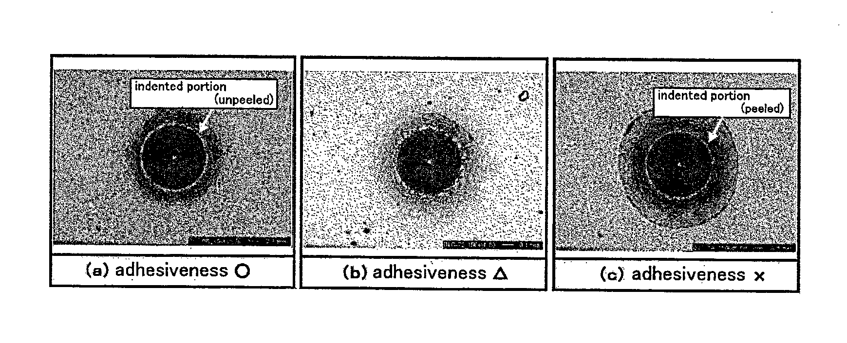
[0203]When a diamond indenter was stricken into base materials of specimens at a load of 150 kg, a peeling generation situation on the periphery of an indenter was observed. Based on the observed peeling generation situations, the adhesiveness of each specimen to the base material was evaluated by an evaluation criterion shown in FIG. 15. Specimens which had a small generation amount of peeling as shown in FIG. 15(a) were evaluated as excellent in the adhesiveness thereof to the base material, and they were recorded as “∘”. Specimens in which peeling occurred partly as shown in FIG. 15(b) were evaluated as inferior in the adhesiveness thereof to the base material, and they were recorded as “Δ”. Specimens in which peeling occurred on the entire circumference of the indenter as shown in FIG. 15(c) were evaluated as significantly inferior in the adhesiveness thereof to the base material, and they were recorded as “x”.
TABLE 10 Film formation example 4-1 4-2 4-3 4-4 4-5 4-6 Base material1) SUS SUS SUS SUS SUS SUJ2 Hardness Hv of base material 650 650 650 650 650 780 Surface roughness μmRa of base material 0.005 0.005 0.005 0.005 0.005 0.005 Whether surface treatment was made — — — — — — (“◯”: treated, “—”: not treated) Hardness Hv of nitrided layer — — — — — — Material of foundation layer Cr Cr Cr Cr Cr Cr Material2) (used in combination with DLC) WC WC WC WC WC WC Whether gradient portion3) was formed (“◯”: ◯ ◯ ◯ ◯ ◯ ◯ formed, “—”: not formed) Film-forming condition of surface layer Introduction ratio4) of methane gas 3.0 1.0 5.0 1.5 1.0 3.0 Vacuum degree (Pa) 0.25 0.25 0.25 0.45 0.80 0.25 Bias voltage (negative) applied to base 100 100 100 150 100 100 material (V) Specific wear amount (×10−10 mm3/(N/m)) 100 80 145 135 130 100 Indentation hardness Average value (GPa) 29.5 36.4 26.4 27.7 26.7 29.7 Standard deviation (GPa) 5.2 6.3 4.9 3.4 3.0 5.0 Average value + standard deviation (GPa) 34.7 42.7 31.3 31.1 29.7 34.7 Critical peeling load (N) 68 68 69 69 67 70 Rockwell indentation test ◯ ◯ ◯ ◯ ◯ ◯ Film thickness (μm) 1.4 1.2 1.4 1.2 1.2 1.4 Ratio5) of thickness of surface layer to 0.70 0.70 0.74 0.70 0.70 0.70 that of hard film Film formation example 4-7 4-8 4-9 4-10 4-11 Base material1) S53C SUS SUS SUS Ultra-hard Hardness Hv of base material 650 650 650 650 650 Surface roughness μmRa of base material 0.005 0.045 0.005 0.005 0.005 Whether surface treatment was made — — ◯ — — (“◯”: treated, “—”: not treated) Hardness Hv of nitrided layer — — 1000 — — Material of foundation layer Cr Cr Cr Cr Cr Material2) (used in combination with DLC) WC WC WC WC WC Whether gradient portion3) was formed (“◯”: ◯ ◯ ◯ ◯ ◯ formed, “—”: not formed) Film-forming condition of surface layer Introduction ratio4) of methane gas 3.0 3.0 3.0 3.0 3.0 Vacuum degree (Pa) 0.25 0.25 0.25 0.25 0.25 Bias voltage (negative) applied to base 100 100 100 100 100 material (V) Specific wear amount (×10−10 mm3/(N/m)) 100 100 100 135 125 Indentation hardness Average value (GPa) 29.5 28.5 29.8 26.4 26.8 Standard deviation (GPa) 5.3 4.5 5.1 2.0 2.0 Average value + standard deviation (GPa) 34.8 33.0 34.9 28.4 28.8 Critical peeling load (N) 68 60 70 65 65 Rockwell indentation test ◯ ◯ ◯ ◯ ◯ Film thickness (μm) 1.4 1.4 1.4 2.8 2.8 Ratio5) of thickness of surface layer to 0.70 0.70 0.70 0.70 0.70 that of hard film 1)SUS, SUS440C, SUJ2: SUJ2, S53C: S53C, ultra-hard:cemented carbide 2)mixed layer in which DLC was used in combination. In the case “WC”, mixed layer consists of WC/DLC. “—” means that mixed layer was not formed. 3)DLC gradient part in surface layer 4)“—” means that only Ar gas was used. Introduction ratio of methane gas shows ratio of introduction amount of methane gas to 100 which was introduction amount of Ar gas. 5)Film thickness of surface layer with respect to entire film thickness
TABLE 11 Film formation example 4-12 4-13 4-14 4-15 Base material1) SUS Ultra- SUS SUS hard Hardness Hv of base material 650 650 650 650 Surface roughness μmRa of base 0.005 0.005 0.005 0.005 material Whether surface treatment was — — — — made (“◯”: treated, “—”: not treated) Hardness Hv of nitrided layer — — — — Material of foundation layer Cr W Ti Cr Material2) (used in combination — WC WC Cr with DLC) Whether gradient portion3) was ◯ ◯ ◯ ◯ formed (“◯”: formed, “—”: not formed) Film-forming condition of surface layer Introduction ratio4) of methane gas 3.0 3.0 3.0 3.0 Vacuum degree (Pa) 0.25 0.25 0.25 0.25 Bias voltage (negative) applied 100 100 100 100 to base material (V) Specific wear amount 6) 110 100 120 (×10−10 mm3/(N/m)) Indentation hardness Average value (GPa) 29.9 29.4 29.4 29.0 Standard deviation (GPa) 4.5 5.5 4.9 5.1 Average value + standard deviation 34.4 34.9 34.3 34.1 (GPa) Critical peeling load (N) 28 60 50 65 Rockwell indentation test X Δ Δ Δ Film thickness (μm) 1.8 2.6 2.2 2.9 Ratio5) of thickness of surface 0.78 0.70 0.71 0.72 layer to that of hard film 6) Because peeling occurred during test, specific wear amount was unmeasurable.
TABLE 12 Film formation example 4-16 4-17 4-18 4-19 4-20 4-21 4-22 Base material1) SUJ2 Ultra- SUS SUS SUS SUS SUS hard Hardness Hv of base material 210 650 650 650 650 650 650 Surface roughness μmRa of base material 0.005 0.005 0.005 0.005 0.005 0.005 0.005 Whether surface treatment was made — — — — — — — (“◯”: treated, “—”: not treated) Hardness Hv of nitrided layer — — — — — — — Material of foundation layer Cr Cr Cr Cr Cr Cr Cr Material2) (used in combination with DLC) WC WC WC WC WC WC WC Whether gradient portion3) was formed (“◯”: ◯ ◯ ◯ ◯ ◯ ◯ ◯ formed, “—”: not formed) Film-forming condition of surface layer Introduction ratio4) of methane gas 3.0 — 10.0 3.0 3.0 3.0 3.0 Vacuum degree (Pa) 0.25 0.80 0.50 0.14 1.05 0.25 0.25 Bias voltage (negative) applied to base 100 100 100 100 100 50 250 material (V) Specific wear amount (×10−10 mm3/(N/m)) 100 240 330 7) 220 310 200 Indentation hardness Average value (GPa) 27.0 19.0 22.0 7) 16.0 20.0 31.0 Standard deviation (GPa) 3.5 2.0 1.5 7) 1.0 3.0 2.0 Average value + standard deviation (GPa) 30.5 21.0 23.5 7) 17.0 23.0 33.0 Critical peeling load (N) 30 40 45 7) 50 48 36 Film thickness (μm) 1.4 2.8 2.4 7) 1.5 2.4 1.1 Ratio5) of thickness of surface layer to 0.70 0.71 0.74 7) 0.71 0.71 0.90 that of hard film 7) Because discharge did not occur, film could not be formed.
[0204]As shown in table 10, it is understood that the hard films of the film formation examples were excellent in the wear resistance and adhesiveness thereof to the base material. In the film formation examples 4-12 through 4-15 in which the structures of the foundation layers and the intermediate layers were different from the structures of the foundation layers and the intermediate layers of the film formation examples 4-1 through 4-11, peeling occurred in the Rockwell indentation test.
[0205]To check the durability of the dimension-measuring jig, the following tests were conducted.
[0206]A test of passing stopper gauges, made of SUJ2 (Vickers hardness Hv: 780), which have a dimension of (φ22 mm×φ8 mm×t6 mm through a hole with φ8 was conducted. The inside diameter of each sintered metal part (copper-iron) used in the test was so adjusted as to be within φ8.01 mm±0.01 mm. The stopper gauges (φ8 mm±0.005 mm×L50 mm, Ra=0.01 μmm, roundness: 0.001 mm) surface-treated in the conditions shown in table 13 were passed through the inside diameter portion of each sintered metal part to check the inside diameter thereof. Because the stopper gauge slides on the inside diameter portion of the sintered metal part, the stopper gauge is damaged and wear with an increase in the number of pass-through times. To measure the roundness, Talyrond 365 produced by Taylor Hobson Ltd. was used. The pass-through test was conducted on 1,000,000 sintered metal parts. Stopper gauges having less than 0.002 mm (amount of change: less than 0.001 mm) in the roundness thereof were recorded as “∘”. Stopper gauges having 0.002 mm to 0.004 mm in the roundness thereof were recorded as “Δ.”. Stopper gauges having more than 0.004 mm in the roundness thereof were recorded as “x”. Table 13 shows the results.
[0207]A test of passing stopper gauges, made of SUJ2 (Vickers hardness Hv: 780), which have a dimension of (φ50 mm×φ100 mm×t50 mm through a hole with φ50 was conducted. The inside diameter of each housing made of FC200 used in the test was so adjusted as to be within φ50 (0.000 to +0.02 mm). The stopper gauges (φ50 mm±0.002 mm×L80 mm, Ra=0.5 μmm) surface-treated in the conditions shown in table 13 were passed through the housing to check the inside diameter thereof. Because the stopper gauge slides on the inside diameter portion of the housing, the stopper gauge is damaged and wear with an increase in the number of pass-through times. The pass-through test was conducted on 100,000 houses. Stopper gauges having less than 0.002 mm (amount of change: less than 0.001 mm) in the roundness thereof were recorded as “∘”. Stopper gauges having 0.002 mm to 0.004 mm in the roundness thereof were recorded as “Δ”. Stopper gauges having more than 0.004 mm in the roundness thereof were recorded as “x”. Table 13 shows the results.
[0208]By using a vernier caliper, made of SUS304 (Vickers hardness Hv: 780), which has an operation portion having a dimension of 0 to 150 mm (dimension-measuring flat portion of indenter: 4 mm×10 mm, surface roughness of flat portion: 0.005 μm, dimension of product is measured at this portion, and force of pressing vernier caliper against product when dimension of product is measured: 100 g), the outside diameters of 1,000,000 outer rings of a bearing corresponding to 608 bearing were measured to observe the frictional situation of the flat portion of the vernier caliper. By using a surface roughness measuring instrument (Form•Talysurf PG1830 produced by Taylor Hobson Ltd.), wear depths with respect to the reference surface was computed. Vernier calipers which had wear depths of less than 1 μm were recorded as “∘”. Those which had wear depths of not less than 1 μm and less than 3 μm were recorded as “Δ”. Those which had wear depths of not less than 3 μm were recorded as “x”. Table 13 shows the results.
TABLE 13 Result of No. Film-forming condition Model part Evaluation method evaluation 1 Same as that of film Stopper gauge A Stopper gauge test A ◯ 2 formation example 4-1 Stopper gauge B Stopper gauge test B ◯ 3 Vernier caliper Vernier caliper measuring test ◯ 4 Same as that of film Stopper gauge A Stopper gauge test A ◯ 5 formation example 4-3 Stopper gauge B Stopper gauge test B ◯ 6 Vernier caliper Vernier caliper measuring test ◯ 7 Same as that of film Stopper gauge A Stopper gauge test A ◯ 8 formation example 4-9 Stopper gauge B Stopper gauge test B ◯ 9 Vernier caliper Vernier caliper measuring test ◯ 10 Untreated (film is not Stopper gauge A Stopper gauge test A X 11 formed on surface) Stopper gauge B Stopper gauge test B X 12 Vernier caliper Vernier caliper measuring test X 13 Same as that of film Stopper gauge A Stopper gauge test A X 14 formation example 4-14 Stopper gauge B Stopper gauge test B Δ 15 Vernier caliper Vernier caliper measuring test Δ
[0209]As shown in table 13, it is understood that even after the dimensions of 100,000 to 1,000,000 products were measured by the dimension-measuring jig, the dimension-measuring jig on which the hard film having the predetermined structure was formed had a small amount of deformation and can be made much longer in the life length thereof than conventional dimension-measuring jigs.
INDUSTRIAL APPLICABILITY
[0210]The rolling bearing of the present invention is excellent in the peeling resistances of the hard film, containing the DLC film, which is formed on the raceway of the inner and outer rings and the rolling contact surfaces of the rolling elements and thus the intrinsic properties of the DLC film can be displayed. Thereby the rolling bearing of the present invention is excellent in its resistance to seizing, wear, and corrosion. Therefore the rolling bearing of the present invention is applicable to various uses including uses in a strict lubrication state.
EXPLANATION OF REFERENCE NUMERALS AND SYMBOLS
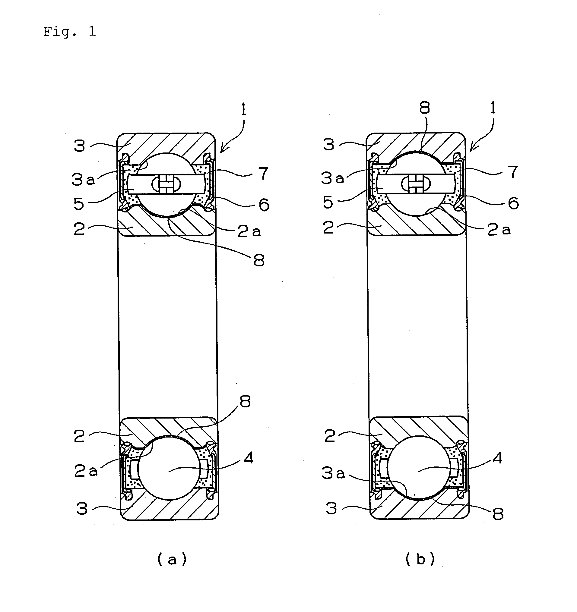
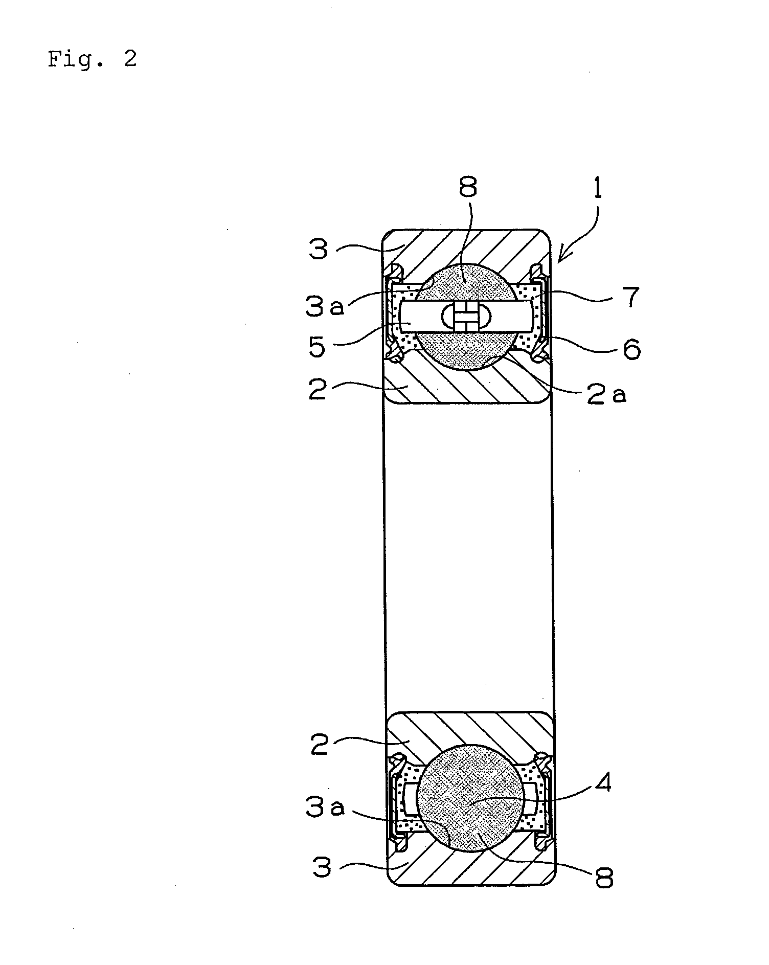
[0211] 1: rolling bearing [0212] 2: inner ring [0213] 3: outer ring [0214] 4: rolling element [0215] 5: cage [0216] 6: sealing member [0217] 7: grease [0218] 8: hard film [0219] 11: bias power source [0220] 12: base material [0221] 13: film (layer) [0222] 15: target [0223] 16: magnetic field lines [0224] 17: Ar ion [0225] 18: ionized target [0226] 19: high-density plasma [0227] 21: vaporization source material [0228] 22: disk [0229] 23: base material [0230] 24: sputter vaporization source material [0231] 31: specimen [0232] 32: mating material [0233] 33: arm portion [0234] 34: load [0235] 35: load cell [0236] 51: specimen [0237] 52: rolling element [0238] 53: aligning ball [0239] 54: rotary ball spline [0240] 55: bearing washer [0241] 56: heater [0242] 57: thermocouple [0243] 61: specimen bearing [0244] 62: load-applying ball bearing [0245] 63: load-applying coil spring [0246] 64: driving pulley [0247] 65: shaft [0248] 71: specimen bearing [0249] 72: pulley [0250] 73: load-applying coil spring [0251] 74: cartridge heater [0252] 75: thermocouple

PUM

PropertyMeasurementUnit
Thickness5.0E-7 ~ 3.0E-6m
Force50.0N
Pressure5.0E8Pa

Description & Claims & Application Information

We can also present the details of the Description, Claims and Application information to help users get a comprehensive understanding of the technical details of the patent, such as background art, summary of invention, brief description of drawings, description of embodiments, and other original content. On the other hand, users can also determine the specific scope of protection of the technology through the list of claims; as well as understand the changes in the life cycle of the technology with the presentation of the patent timeline. Login to view more.

Similar technology patents

Ducument feeder and image reading apparatus with the same

InactiveUS20050035527A1simple structurelittle damage
Owner:NISCA KK

Thermoplastic elastomer composition

ActiveUS20170247535A1superior adhesiveness
Owner:SUMITOMO CHEM CO LTD

Highly filled back surface field aluminum paste for point contacts in perc cells and preparation method thereof

ActiveUS20190156966A1little damageelectrical performance be improve
Owner:NANTONG T SUN NEW ENERGY CO LTD

Classification and recommendation of technical efficacy words

  • superior adhesiveness
  • little damage

Thermoplastic elastomer composition

ActiveUS20170247535A1superior adhesiveness
Owner:SUMITOMO CHEM CO LTD

Ducument feeder and image reading apparatus with the same

InactiveUS20050035527A1simple structurelittle damage
Owner:NISCA KK

Highly filled back surface field aluminum paste for point contacts in perc cells and preparation method thereof

ActiveUS20190156966A1little damageelectrical performance be improve
Owner:NANTONG T SUN NEW ENERGY CO LTD
Why Eureka
Try Eureka