Battery electrode production method

Active Publication Date: 2013-01-24
TOYOTA JIDOSHA KK
View PDF4 Cites 8 Cited by
  • Summary
  • Abstract
  • Description
  • Claims
  • Application Information

AI Technical Summary

Benefits of technology

[0014]In a preferable aspect of the production method disclosed herein, the polymer protrusions are formed by coating a polymer solution containing a polymer onto the current collector followed by drying. In this case, the polymer protrusions can be formed easily. For example, polymer protrusions in the form of dots can be easily formed by coating the polymer solution by spraying. In addition, polymer protrusions in the form of patterned projections can be formed easily by coating the polymer solution by printing (such as inkjet printing, relief printing, gravure printing or screen printing).
[0015]In a preferable aspect of the production method disclosed herein, static electricity is applied to a coating of the polymer solution. In this case, the drying rate of the coating of the polymer solution is accelerated by energy of the static electricity. Consequently, the polymer protrusions can be formed efficiently (and preferably without the use of a drying oven).
[0016]In a preferable aspect of the production method disclosed herein, the polymer protrusions function as a binder in the compound material layer. In this case, since the polymer protrusions function as a binder, adhesion between the compound material layer and the current collector can be further enhanced. In this case, the polymer protrusions can be made of the same material (common po

Problems solved by technology

However, in the production of a negative electrode as described above, when a compound material paste containing a negative electrode active material powder and a binder is coated onto a negative electrode current collector and dried, convection occurs during drying, and since binder in the vicinity of the current collector gathers (rises up) in the surface layer portion of the object coated with paste (opposite side of the current collector), the amount of the binder in the vicinity of the current collector decreases, thereby resulting in the problem of a decrease in adhesive stre

Method used


Image

  • Battery electrode production method
  • Battery electrode production method
  • Battery electrode production method

Examples


Embodiment Construction

[0031]The following provides an explanation of embodiments according to the present invention while referring to the drawings. In the following drawings, those members and sites demonstrating the same actions are explained using the same reference symbols. Furthermore, the dimensional relationships in each drawing (such as length, width and thickness) do not reflect actual dimensional relationships. In addition, matters other than those specifically mentioned in the present description that are required for carrying out the present invention (such as the configuration and production method of an electrode body provided with a positive electrode and negative electrode, the configuration and production method of a separator and electrolyte, batteries, or other general technical matters relating to battery construction) can be understood to be design matters for a person with ordinary skill in the art based on the prior art in the relevant field.

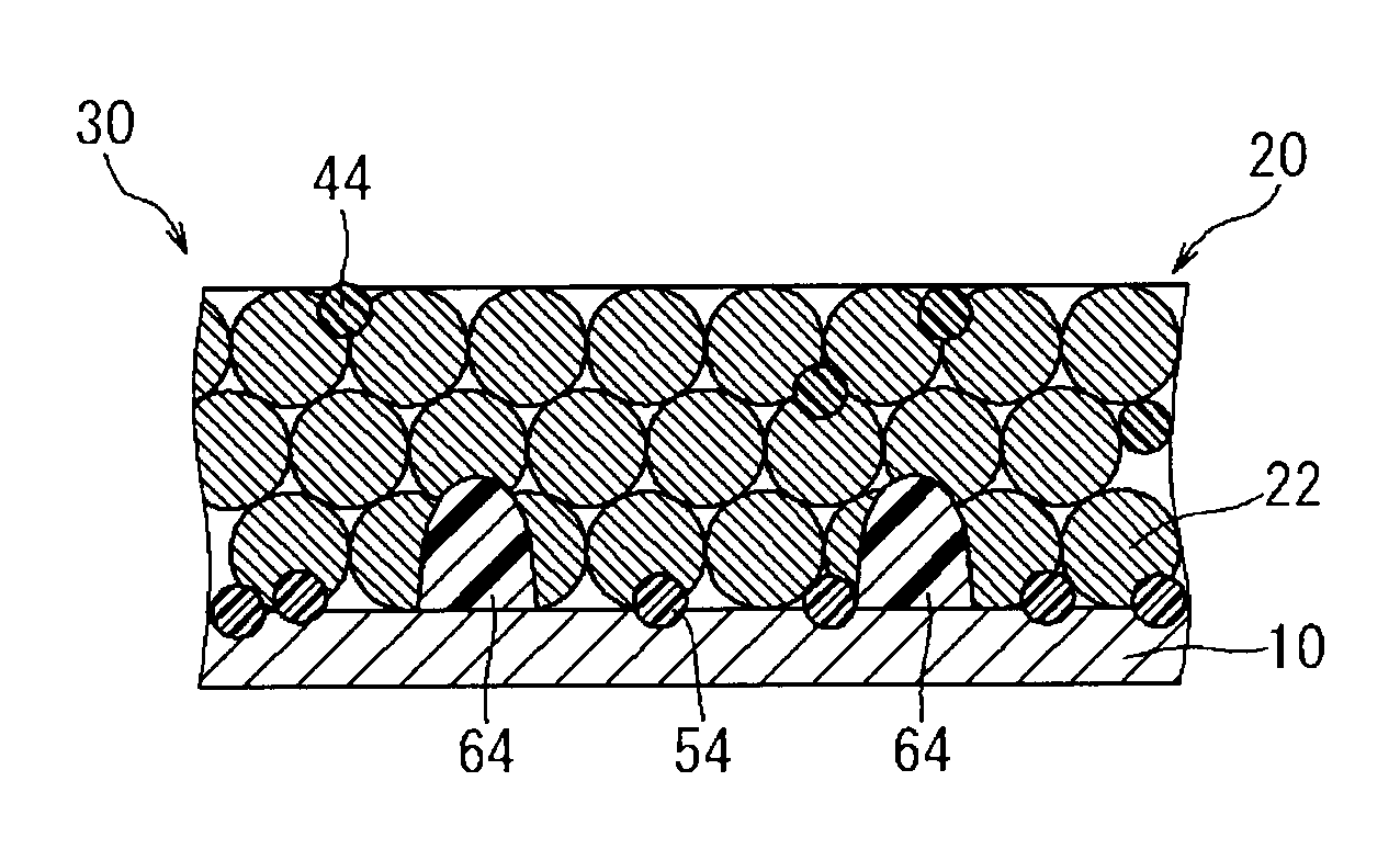
[0032]As shown in FIG. 1, the electrode ...


PUM


Abstract

The present invention provides a method for producing a battery electrode having a configuration in which a compound material layer containing an active material 22 and a binder 54 is retained on a current collector 10. This method includes a step of forming protrusions 64 composed of a polymer on a surface of the current collector 10, a step of forming a binder solution layer 56 by coating a binder solution 50 containing the binder 54 over the polymer protrusions 64 onto the current collector 10, a step of depositing the binder solution layer 56 and a compound material paste layer 46 on the current collector 10 by applying a compound material paste 40 containing the active material 22 over the binder solution layer 56, and a step of obtaining an electrode in which the compound material layer is formed on the current collector 10 by drying both the deposited binder solution layer 56 and compound material paste layer 46.

Description

TECHNICAL FIELD[0001]The present invention relates to a method for producing a battery electrode, and more particularly, to a method for producing a battery electrode having a configuration in which an electrode compound material layer containing an electrode active material is retained on a current collector.BACKGROUND ART[0002]Lithium ion batteries, nickel hydrogen batteries and other secondary batteries have recently become increasing important for use as vehicle-mounted power supplies or power supplies of personal computers and portable terminals. In particular, lithium secondary batteries, which are lightweight and provide high energy density, are expected to be preferably used as vehicle-mounted, high-output power supplies. In a typical configuration of this type of secondary battery, an electrode is provided that has a configuration in which a material capable of reversibly occluding and releasing lithium ions (electrode active material) is retained on an electrically conduct...

Claims


Application Information

Patent Timeline
IPC IPC(8): B05D5/12H01M4/64H01M4/13H01M4/139
CPCH01M4/0404H01M4/0473H01M4/1391H01M4/621H01M4/366H01M4/667H01M4/70Y02E60/122H01M4/66Y02E60/10Y02P70/50
Inventor UCHIDA, YOZOYAMAZAKI, NOBUYUKI
Owner TOYOTA JIDOSHA KK
Why Eureka
Try Eureka