Enhanced resolution imaging systems for digital radiography

Active Publication Date: 2013-01-31
MINNESOTA IMAGING & ENG
View PDF3 Cites 46 Cited by
  • Summary
  • Abstract
  • Description
  • Claims
  • Application Information

AI Technical Summary

Benefits of technology

[0006]Small area imaging applications such as spot mammography may be implemented using a small focal spot source along with several options for coded aperture use. Either employ pre-subject and pre-detector masks or no masks at all. For a small area imaging application such as oral dentistry a pre-object mask and the pre-detector mask can be packaged into a rigid frame such that the detector and pre-detector mask fit inside the mouth while the aligned pre-object mask is located outside the mouth. The package can then be aligned by optical or mechanical means with the small focal spot of the radiation source. The advantage of magnification is lost since the detector is close to the object being imaged. Oral dentistry imaging with PCI capability can be implemented with digital cameras detectors and storage phosphor plate (or screen) detectors as well as structured radiation detectors.
[0007]The invention provides dual-use capabilities for digital slit scanning, slot scanning and CT scanning systems. An attenuation image can be acquired, a PCI image can be acquired, or both can be acquired using a dual imaging system using any of these scanning formats. One option is to acquire a full image of the object with one imaging technique and then acquire a small image of a questionable region of the object using the other imaging technique (the same or different radiation beam energy spectrum and radiation beam size may be employed) for additional information. For high resolution slit scanning a small focal spot source can be used alone or be combined with 1-D pre-object and pre-detector masks which can be moved into or out of the x-ray beam path based on the image requirements. Furthermore, an adjustment of the slits such that the projection of the x-ray beam from the pre-object slit overlaps the pre-detector slit can be used to extend the PCI effect from 1-D to 2-D. A 1-D PCI effect can be implemented with only the slits by adjusting the slits such that the radiation beam from the pre-object slit slightly overlaps the pre-detector slit to enable a 1-D PCI effect. The radiation source-detector distance can be altered to achieve the desired level of magnification for PCI. Slot scanning can employ movable 2-D pre-object and pre-detector masks that incorporate a selection of aperture dimensions that can be used to tune the PCI effect as needed. Multiple sets of slits or slots can be employed to increase radiation source utilization efficiency. The slit detector linear array geometry with respect to the x-ray beam can be face-on, edge-on, or near-edge-on (tilted edge-on). In those implementations in which either edge-on or near-edge-on (tilted edge-on) detector geometries are acceptable the detector geometry will simply be referred to as edge-on. The choice of detector may depend on the x-ray source(s) and operational energy spectrum(s) employed. A face-on or edge-on gas, scintillator, semiconductor or structured detector may be suitable if it offers adequate spatial resolution and detection efficiency along with appropriate integration or photon counting or energy resolution capability. Structured detectors include structured cell detectors (which typically incorporate materials such as quantum dots or an amorphous semiconductor) as well as detectors such as 3-D semiconductor detectors (see Da Via C, Nucl. Instru. Meth. A, vol. 594, p. 7-12, 2008). In some applications an edge-on detector geometry may be preferred to a face-on detector geometry for a particular type of detector. The detection efficiency of a thin, structured (structured cell) quantum dot detector

Problems solved by technology

PCI limitations typically include reduced tube output as focal spot size decreases and reduced detection efficiency if the active pixel area is reduced.
PCI images, as with conventional digital x-ray images, suffer from the effects of attenuation (absorption, scattering) and variable magnification for a thick object, as well as from the effects of overlapping structures and nonuniformities in the object.
An object such as a breast with a complex tissue structure may represent a challenge in that the contrast gains derived from PCI may also genera

Method used


Image

  • Enhanced resolution imaging systems for digital radiography
  • Enhanced resolution imaging systems for digital radiography
  • Enhanced resolution imaging systems for digital radiography

Examples


Embodiment Construction

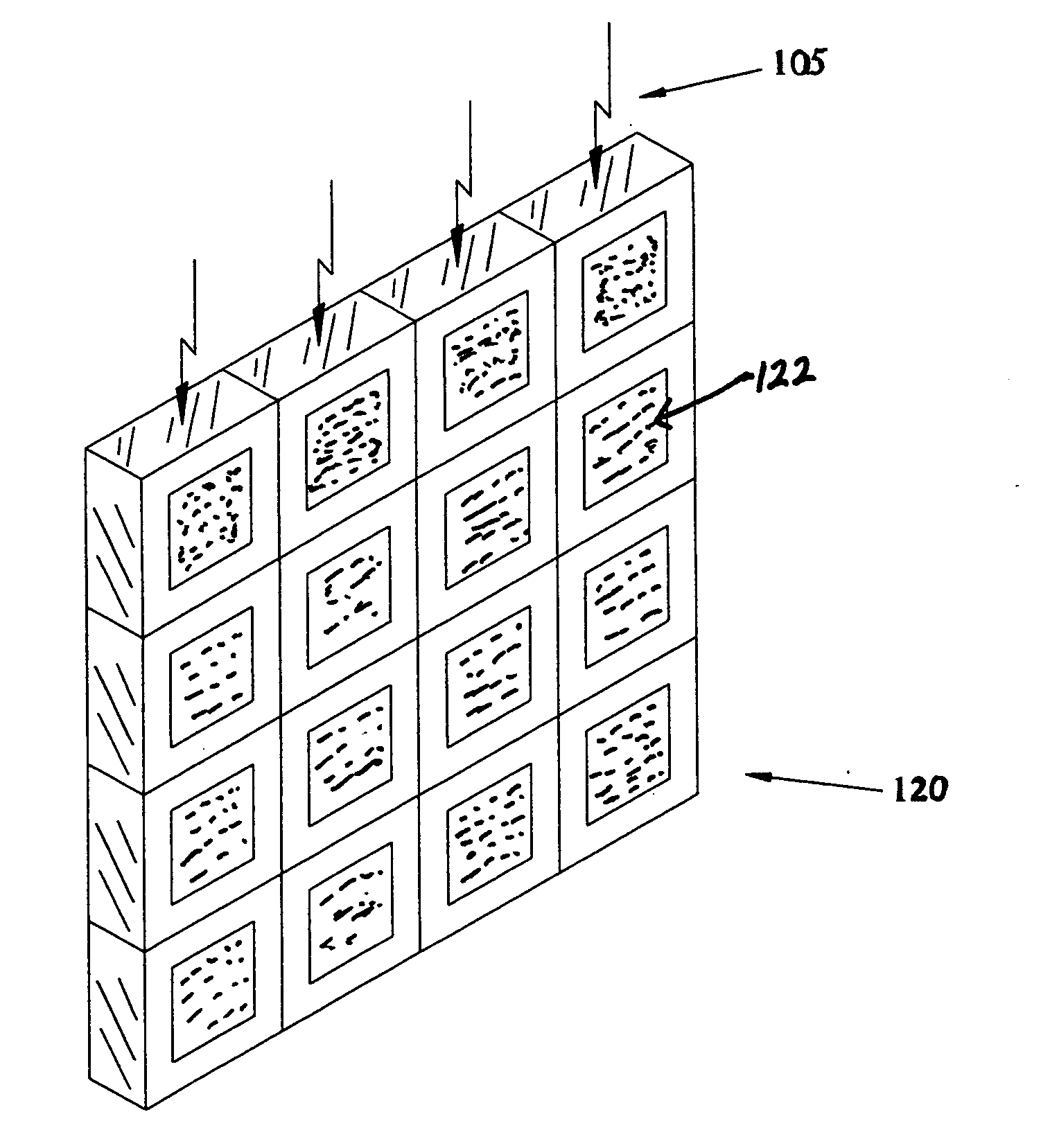
[0018]The invention utilizes existing and new x-ray detector technology and systems to offer either improved PCI capabilities or dual use capabilities (combining capabilities for both PCI and conventional (attenuation) digital x-ray attenuation imaging). One such technology is the storage phosphor plate (or screen) x-ray detector. Storage phosphor plate technology (including nano-particle storage phosphor ceramic plates (uniform and fiber optic plates) capable of extremely high spatial resolution) is suitable for large area and small area medical imaging applications such as digital mammography (see Rowlands J, Phys. Med. Biol., vol. 47, R123-R166, 2002; Johnson J, et al., J. Am. Ceram. Soc. Vol. 90, no. 3, p. 693-698, 2007), spot area (small area) digital mammography, digital tomosynthesis, and digital dentistry (as described in Nelson, U.S. patent application Ser. No. 12 / 930,771, Jan. 18, 2011 and incorporated herein) as well as industrial and scientific applications. For some app...


PUM


Abstract

The invention provides methods and apparatus for enhanced PCI and dual-use radiation imaging systems. In one implementation high resolution storage phosphor plate radiation detector (an area detector) is employed for conventional attenuation radiation imaging and/or PCI (including conventional PCI and coded aperture PCI). Slit and slot scan implementations for dual-use systems are introduced. Dedicated single and dual-use slit and slot scan system for conventional attenuation imaging and PCI are described that employ face-on or edge-on detectors. Slit and slot scan systems that employ area detectors are described. Edge-on, structured cell detector designs are described. Applications of edge-on structured cell detectors for CT, Nuclear Medicine, PET, and probe detectors are described.

Description

FIELD OF THE INVENTION[0001]This invention provides novel enhanced resolution imaging systems and designs for use in digital radiography with applications for medical, industrial and scientific imaging.BACKGROUND OF THE INVENTION[0002]Conventional digital x-ray radiographic imaging systems record a representation of the attenuation that x-rays experience while traversing a medium. Detector options include integration, photon counting, and energy resolution capability in geometric configurations that include slit, slot, small area, and full field of view imaging formats. The development of effective image contrast enhancement techniques for digital radiography has taken various forms: optimizing the x-ray source emission spectrum, employing more efficient detectors and detector with photon counting or spectroscopy capability (Nelson, U.S. Pat. No. 4,937,4534), introducing contrast materials into the subject (for example, the human body), using analyzers (Nelson, U.S. Pat. No. 4,969,1...

Claims


Application Information

Patent Timeline
IPC IPC(8): G01N23/04
CPCG01N23/04A61B6/484G01N2223/50G01N23/041H01L27/14601H01L27/14658
Inventor NELSON, ROBERT SIGURDNELSON, WILLIAM BERT
Owner MINNESOTA IMAGING & ENG
Why Eureka
Try Eureka