Cell Isolation Instrument

Active Publication Date: 2013-01-31
NIHON KOHDEN CORP +1
View PDF1 Cites 7 Cited by
  • Summary
  • Abstract
  • Description
  • Claims
  • Application Information

AI Technical Summary

Benefits of technology

[0006]It is therefore an object of the invention to provide a cell isolation instrument in which processes to be performed

Problems solved by technology

Therefore, the technique requires labor and a long time period.
The technique has a further problem in that the cell recovery rate is dispersed because of differences in the mincing process with using a blade and in the permeation rate in

Method used


Image

  • Cell Isolation Instrument
  • Cell Isolation Instrument
  • Cell Isolation Instrument

Examples


Embodiment Construction

[0018]Hereinafter, an embodiment of the invention will be described in detail with reference to the accompanying drawings.

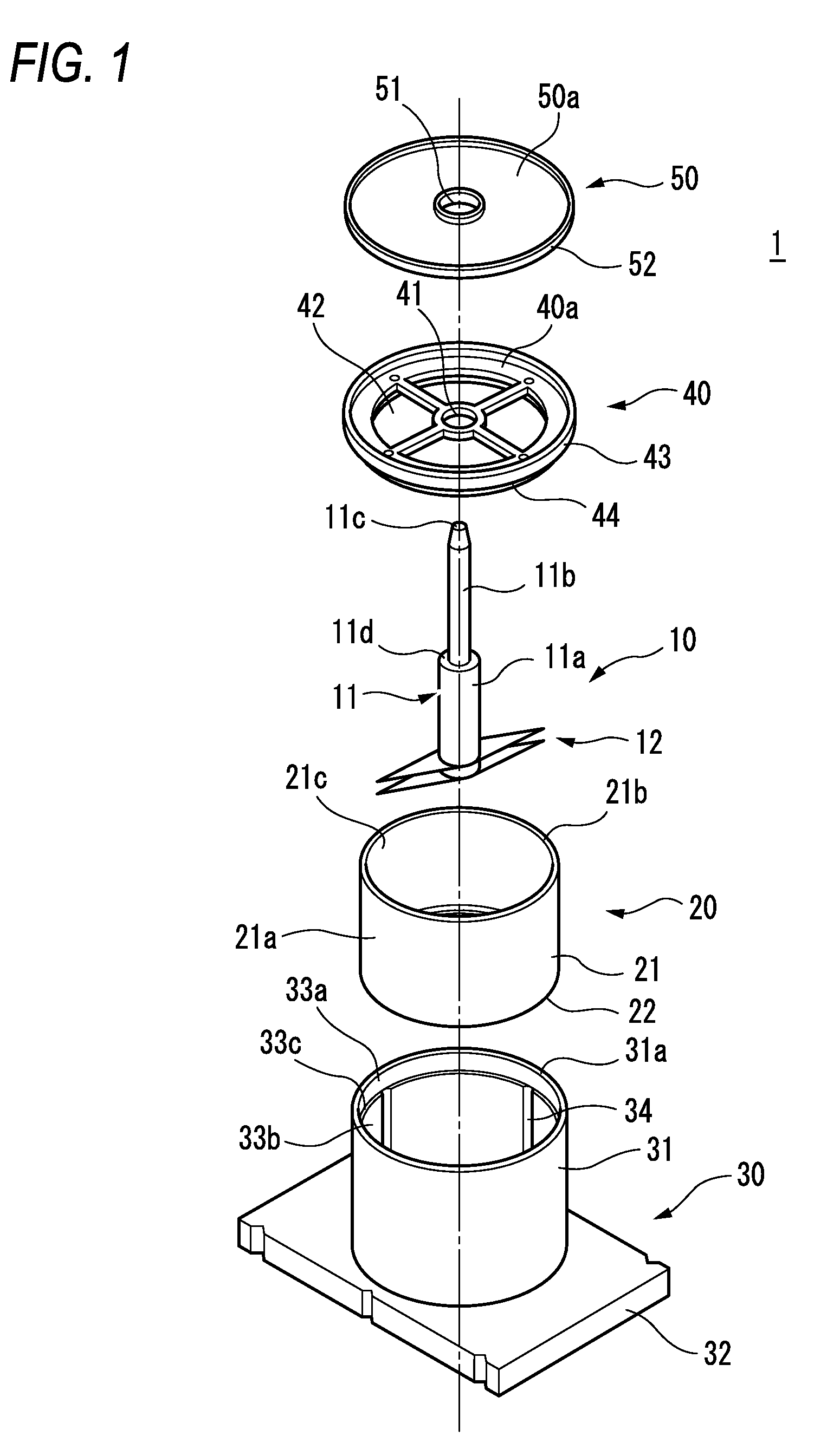
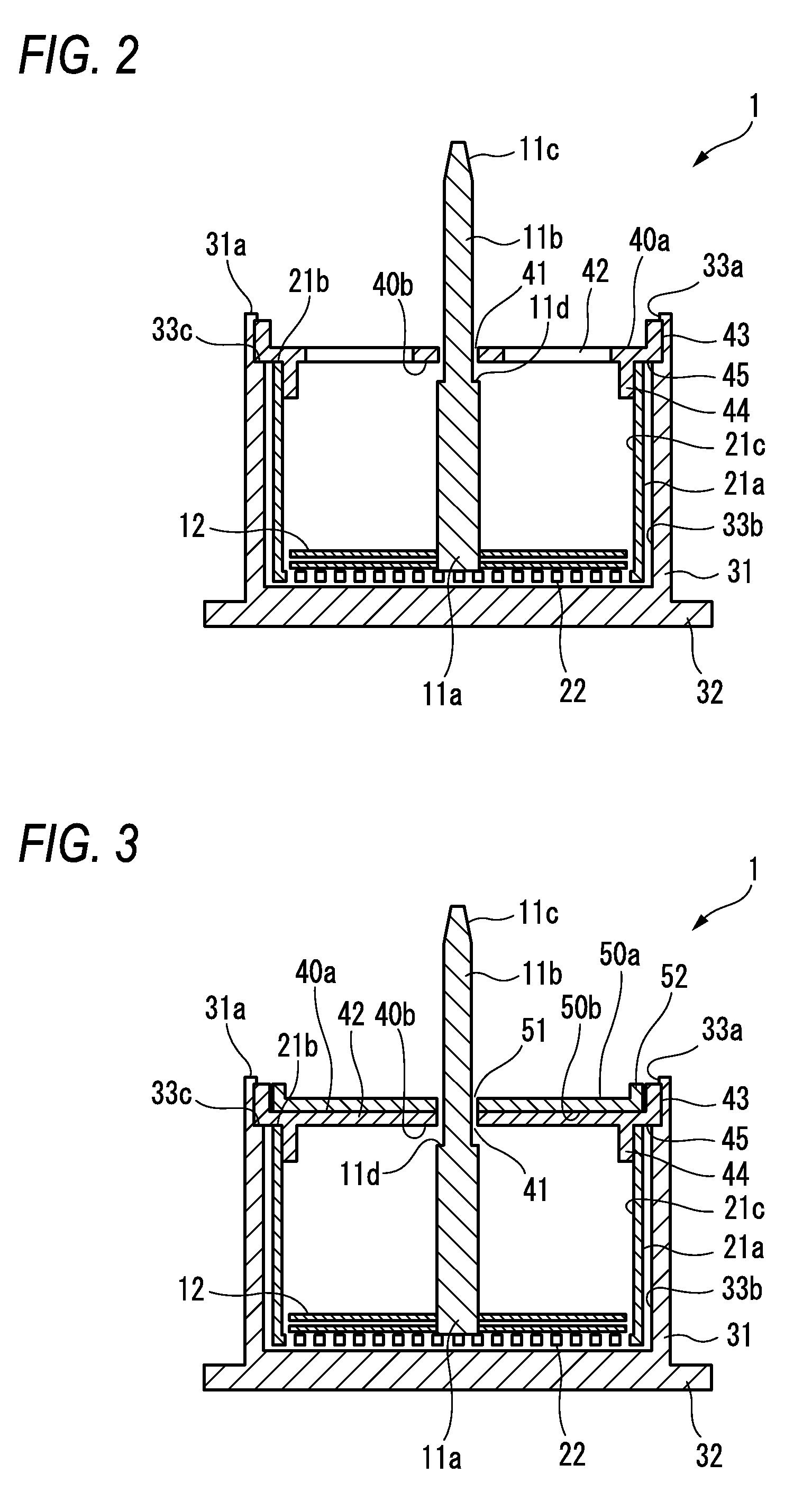
[0019]FIG. 1 shows a state where a cell isolation instrument 1 of an embodiment of the invention is disassembled. The cell isolation instrument 1 includes an isolation member 10, an inner container (first container) 20, an outer container (second container) 30, an inner lid (lid member, first lid member) 40, and an outer lid (lid member, second lid member) 50. These components are formed by a material (such as a resin) which has resistance to ethylene oxide gas sterilization.

[0020]The isolation member 10 includes a shaft member 11 and a plurality of blade members 12. The shaft member 11 includes a large-diameter portion 11a, a small-diameter portion 11b, and a connecting portion 11c. The blade members 12 are supported by the lower end of the large-diameter portion 11a. The diameter of the small-diameter portion 11b is smaller than that of the large-diameter porti...


PUM

PropertyMeasurementUnit
Diameteraaaaaaaaaa

Abstract

A cell isolation instrument includes: a first container which has an opening in an upper portion; a filtration member which defines at least a part of a lower portion of the first container; an isolation member which is movably housed in the first container to collide with a tissue, thereby isolating cells; and a second container which houses the first container in a manner that the first container can be taken out.

Description

BACKGROUND OF THE INVENTION[0001]The present invention relates to a cell isolation instrument which is used in the field of clinics / research of regenerative medicine, or that of cell culture, and more particularly to a cell isolation instrument which is used for isolating cells from a tissue (body tissue) with a high survival rate.[0002]There is a technique in which, in order to obtain isolated living cells, a tissue is minced with a sharp blade, and the minced tissue is subjected to an enzyme process with collagenase or the like to digest the extracellular matrix.[0003]In the technique, procedures of the enzyme process and cell recovery must be repeatedly performed. Therefore, the technique requires labor and a long time period. The technique has a further problem in that the cell recovery rate is dispersed because of differences in the mincing process with using a blade and in the permeation rate in the enzyme process, etc.[0004]JP-T-2007-505631 discloses an apparatus in which the...

Claims


Application Information

Patent Timeline
IPC IPC(8): C12M1/00
CPCC12M45/02
Inventor SHIOYAMA, TAKAHIROSUZUKI, AKANEOKANO, TERUOSHIMIZU, TATSUYAHARAGUCHI, YUJI
Owner NIHON KOHDEN CORP
Why Eureka
Try Eureka