

Battery separator and method of forming same
a battery separator and separator technology, applied in the field of sheet products, can solve the problems of poor tensile strength and puncture strength of porous products, process must be time-consuming, and the porous product cannot be easily manipulated, so as to improve dimensional stability
- Summary
- Abstract
- Description
- Claims
- Application Information
AI Technical Summary
Benefits of technology
Problems solved by technology
Method used
Image

Examples
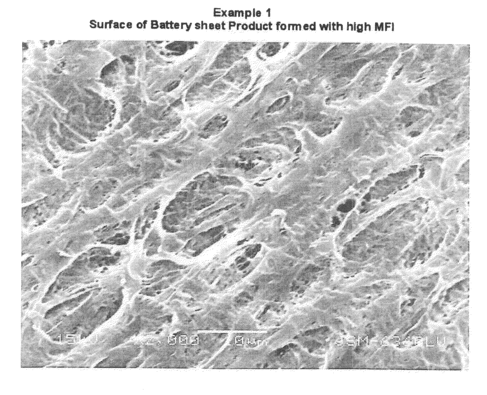
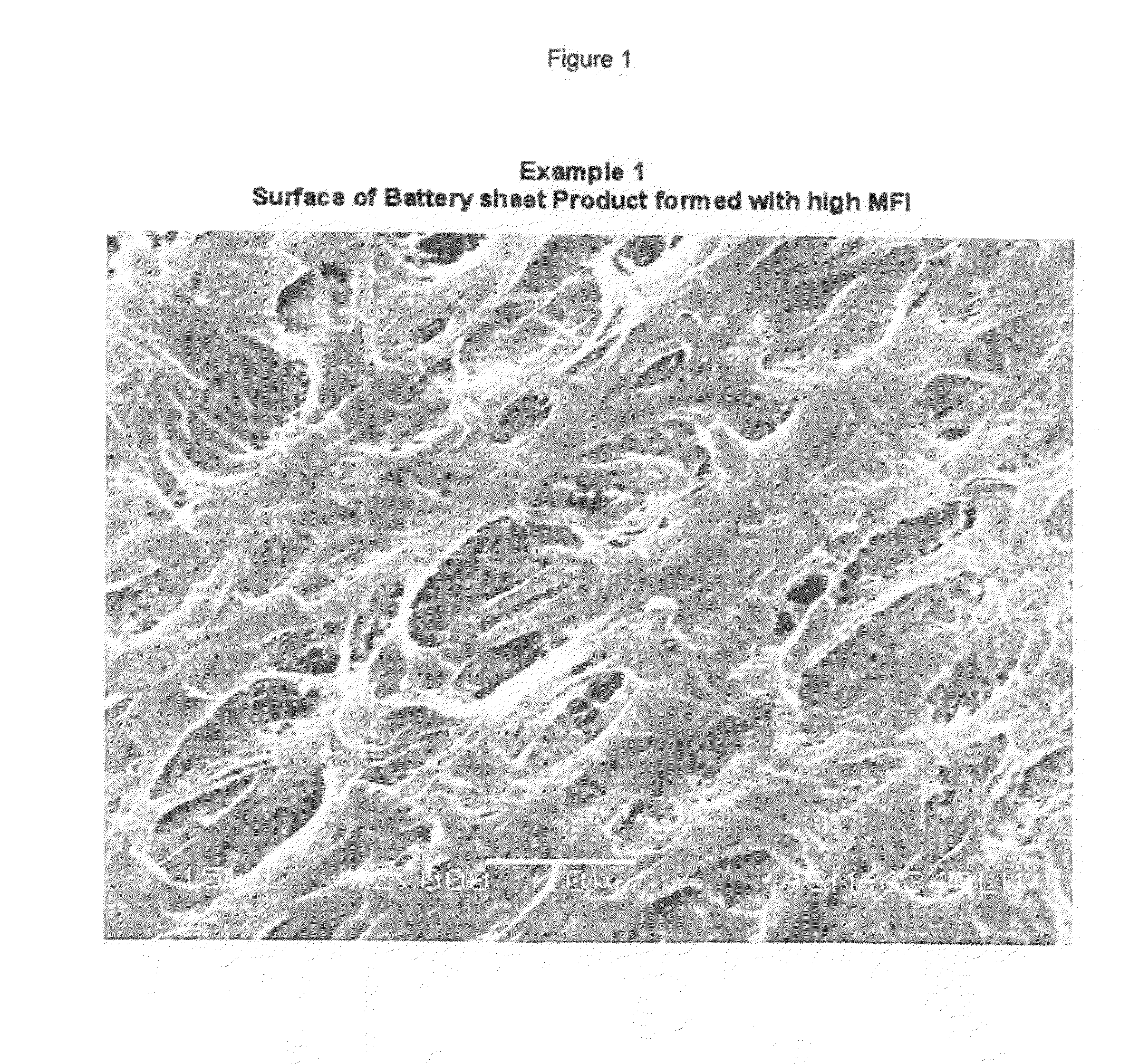
example 1
[0090]Polymer type 19A at 41% was mixed with 59% of MSB fluid in an extruder. The cast film was cooled and subsequently stretched in the machine direction in four sequential steps. The stretch ratios and temperatures are listed in Table 1, indicated as 1.5, 1.4, 1.4 and 1.5 times with the corresponding temperature of 60, 71, 82 and 94° C. (140, 160, 180 and 200° F.), forming the first sheet material. The first sheet material was subsequently stretched in the transverse direction at a ratio of 3.5 times at a temperature of 71° C. (160° F.) for all three zones used (preheat, stretch and heat-anneal). The finished sheet product was tested to contain less than 0.1% of residual fluid. The material exhibited a porosity of 84%, resistance of 30 mohm-cm.sq., resistivity of 6 ohm-cm and a wicking rate of 55 seconds.
[0091]The wicking rate test was conducted using one drop (30 mg) of isopropyl alcohol (IPA) placed on a piece of formed battery separator placed in the horizontal position. The ra...
example 2
[0092]Polymer type L5906 at 36% was mixed with 64% of MSC fluid in an extruder. The cast film was cooled and subsequently stretched in the machine direction in four sequential steps. The stretch ratios and temperatures are listed in Table 1, indicated as 1.5, 1.2, 1.2 and 4 times with the corresponding temperature of 71, 80, 88 and 110° C. (160, 175, 190 and 230° F.), forming the first sheet material. The first sheet material was subsequently stretched in the transverse direction at a ratio of 2.5 times at a temperature of 32, 32 and 110° C. (90, 90 and 230° F.) for the corresponding preheat, stretch and heat-anneal zones. The finished sheet product tested to contain less than 0.1% of residual fluid. The material exhibited a porosity of 57%, resistance of 40 mohm-cm.sq., resistivity of 17 ohm-cm and a wicking rate of 25 seconds. The resulted product had a thickness of 24 microns and 440 gram force puncture strength. The tensile strength performance is listed in Table 1.
example 3
[0093]Polymer type L5906 at 45% was mixed with 55% of MSC fluid in an extruder. The cast film was cooled and subsequently stretched in the machine direction in two sequential steps. The stretch ratios and temperatures are listed in Table 1, indicated as 1.5 and 4 times with the corresponding temperature of 71 and 105° C. (160 and 220° F.), to form the first sheet material. The first sheet material was subsequently stretched in the transverse direction at a ratio of 3 times at a temperature of 32, 49 and 121° C. (90, 120 and 250° F.) of the corresponding preheat, stretch and heat-anneal zones. The finished sheet product tested to contain less than 0.1% of residual fluid. The material exhibited a porosity of 69%, resistance of 54 mohm-cm.sq., resistivity of 16 ohm-cm and a wicking rate of 18 seconds.
Examples 4, 5, 7, 8, 9 and 10
[0094]Polymer L5906 and MSC fluid were melt blended in an extruder. The percentages of compositions and the first machine and second transverse directional str...
PUM
| Property | Measurement | Unit |
|---|---|---|
| Temperature | aaaaa | aaaaa |
| Temperature | aaaaa | aaaaa |
| Temperature | aaaaa | aaaaa |
Abstract
Description
Claims
Application Information