Indium Target And Manufacturing Method Thereof

Active Publication Date: 2013-02-14
JX NIPPON MINING& METALS CORP
View PDF4 Cites 5 Cited by
  • Summary
  • Abstract
  • Description
  • Claims
  • Application Information

AI Technical Summary

Benefits of technology

[0019]The present invention can provide an indium target and manufacturing method thereof, where deposition rate is high, initial di

Problems solved by technology

However, if the indium target, poured into the mold, is cast by leaving it to cool, structures of g

Method used


Image

  • Indium Target And Manufacturing Method Thereof
  • Indium Target And Manufacturing Method Thereof
  • Indium Target And Manufacturing Method Thereof

Examples


Example

Working Example 1

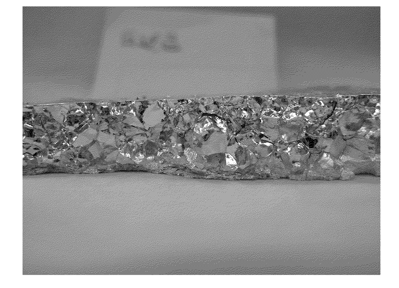
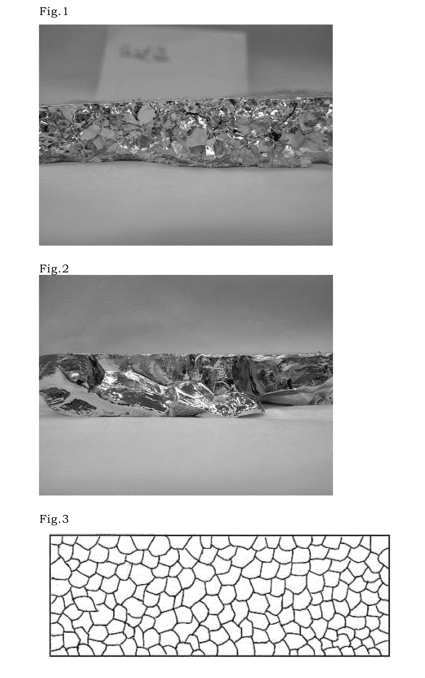
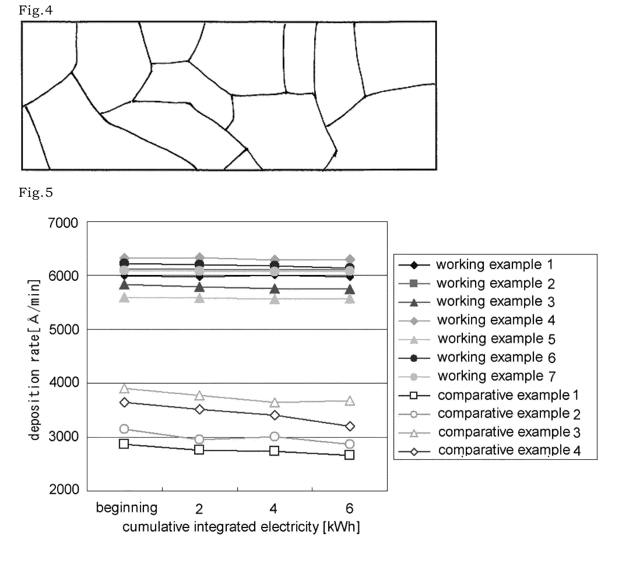
[0038]Raw indium (purity: 4N) melted at 180° C. was poured into a mold made of SUS, of 250 mm long, 160 mm wide, 80 mm deep (inside dimension) to a depth of 39 mm. Next, the mold was cooled with water from the environment and then ingot was produced. Next, the ingot of 39 mm thick was rolled with reducing 3 mm thick each time, and then a tile of 6 mm thick was produced. This tile was cut to be discoid shape of 205 mm in diameter. Next, the tile was bonded on a backing plate, made of copper, of 250 mm in diameter and 5 mm thick, and then produced to be discoid shape of 204 mm in diameter and 6 mm thick with turning machine. In this way, indium target was produced.

Example

[0039]Indium target was produced in a manner similar to the working example 1, except that refrigerant was not used and raw indium in the mold was left to cool.

Example

Working Example 3

[0040]Indium target was produced in a manner similar to the working example 1, except that ingot of 18 mm thick was produced and then a tile of 6 mm thick was produced by rolling with reducing 3 mm thick each time.


PUM

PropertyMeasurementUnit
Fractionaaaaaaaaaa
Fractionaaaaaaaaaa
Electric potential / voltageaaaaaaaaaa

Abstract

The present invention provides an indium target and manufacturing method thereof, where deposition rate is high, initial discharge voltage is low, and deposition rate and discharge voltage, from the start of sputtering to the end of sputtering, are stable. In the indium target, an aspect ratio (length of longer direction/length of shorter direction) of crystal particle, observed from cross-section direction of the target, is 2.0 or less.

Description

TECHNICAL FIELD OF THE INVENTION[0001]The present invention relates to a sputtering target and manufacturing method thereof. In particular, the present invention relates to an indium target and manufacturing method thereof.BACKGROUND OF THE INVENTION[0002]Indium is used as sputtering target for forming photoabsorption layer of Cu—In—Ga—Se system (CIGS system) thin-film solar cell.[0003]Traditionally, as disclosed in Patent document 1, indium target is produced by attaching indium and the like, on a backing plate, and next, setting a mold on the backing plate, and then pouring indium into the mold and casting them.[0004](Patent documents 1) Japanese Examined Patent Publication No. 63-44820SUMMARY OF THE INVENTION[0005]However, there is still room for improvement, in the indium target produced by such traditional melting and casting method, with regard to deposition rate and discharge voltage.[0006]The present invention aims to provide an indium target and manufacturing method thereof...

Claims


Application Information

Patent Timeline
IPC IPC(8): C23C14/06B23P17/00C23C14/34
CPCY10T29/49991C23C14/3414B21B1/02B22D7/00C23C14/34H01J37/3414H01J37/3426
Inventor ENDO, YOUSUKESAKAMOTO, MASARU
Owner JX NIPPON MINING& METALS CORP
Why Eureka
Try Eureka