
Optical device, method for producing optical device, and projection-type imaging apparatus

Inactive Publication Date: 2013-02-14
SEIKO EPSON CORP
View PDF5 Cites 7 Cited by
  • Summary
  • Abstract
  • Description
  • Claims
  • Application Information

AI Technical Summary

Benefits of technology

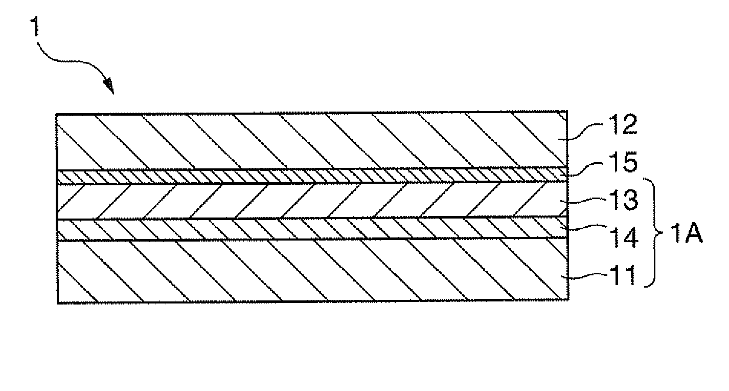
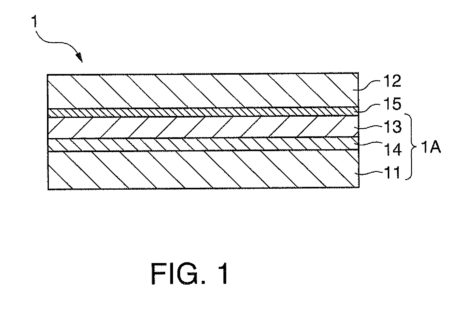
The patent describes a configuration for an optical device with improved bonding and optical properties. A first bonding film is formed of an adhesive layer to bond the first substrate to a resin layer, while a second bonding film is formed of a curable bonding agent to bond the second substrate to the resin layer. The adhesive layer and curable bonding agent shrink after sealing the recess, preventing detachment of the substrates and absorbing irregularities of the resin layer to enhance optical properties. This configuration also results in a long life and excellent optical properties for the optical device. Additionally, the patent describes a projection-type imaging apparatus utilizing this bonding configuration.

Problems solved by technology

An optical device in the related art cannot withstand light of a high luminance lamp and is deteriorated, resulting in decreasing the optical properties such as transmittance.
Alternatively, a problem arises that an optical device, a bonding agent, or the like, which is formed of a resin, is deformed by heat.
That is, a polarizer formed of, as a raw material, an organic film disclosed in JP-A-10-039138, JP-A-2010-117537, or JP-A-2010-191203 has a problem that a defect such as yellow discoloration due to light resulting from increasing the output or decreasing the arc length or heat generated by the light is caused.
However, it was found that when a plasma-polymerized film is used as the bonding film, the thickness of the bonding film is several tens nanometers, for example, in the case of Japanese Patent No. 4337935, an extremely thin film having a thickness of 1 to 10000 nm, preferably 2 to 800 nm is used, and therefore, if both principal surfaces of a film polarizer are sandwiched by inorganic light transmissive substrates, the irregularities of the surface of the film polarizer cannot be completely absorbed because the bonding film is thin, and therefore, an air bubble or the like is incorporated to cause an external appearance defect, resulting in causing an adverse effect on the optical properties such as transmissibility.
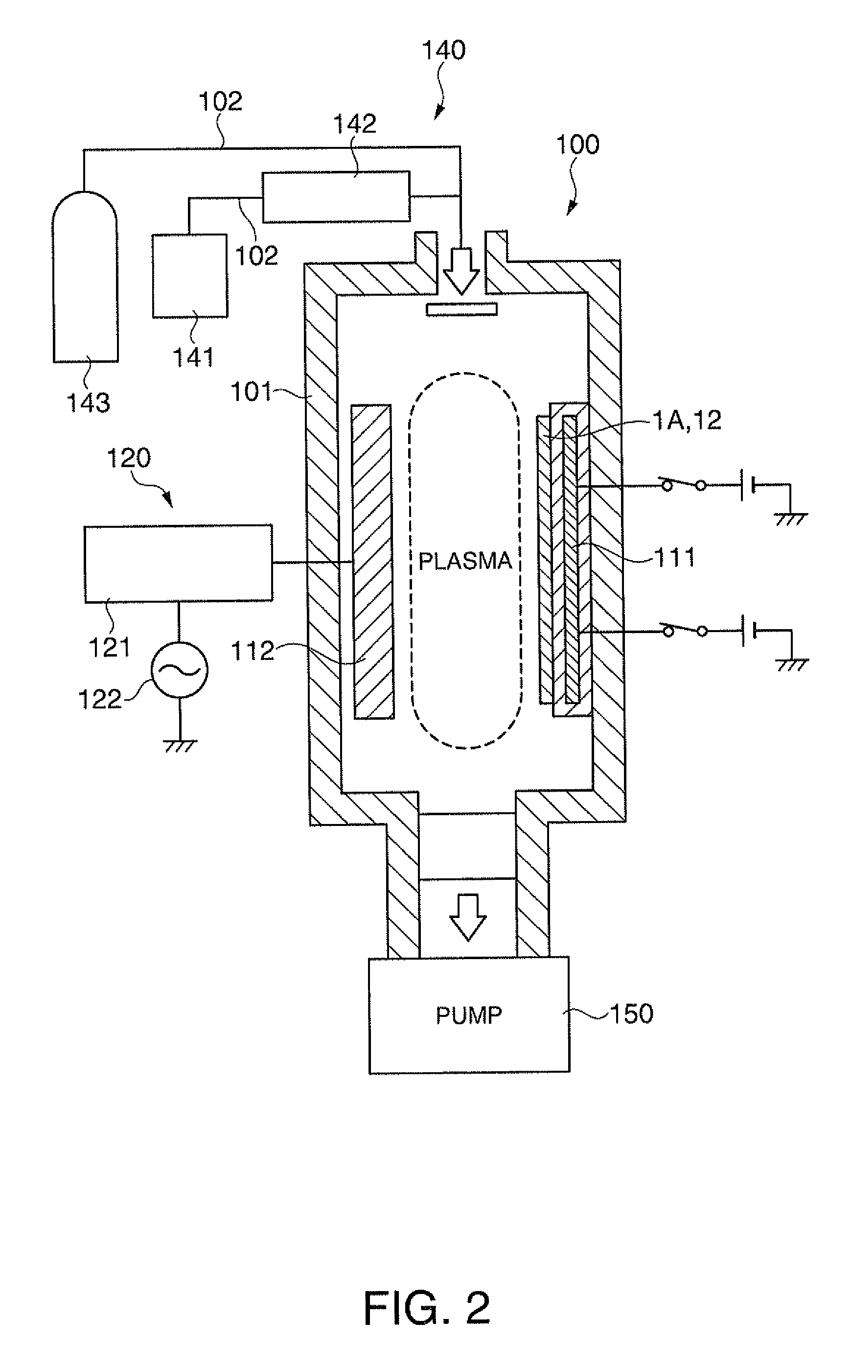
Further, since the bonding film is formed on both principal surfaces of the film polarizer by a plasma polymerization method, the time of exposure of the film polarizer to heat generated by a plasma is long, and therefore, a problem arises that the film polarizer itself is deteriorated or deformed.

Method used


Image

  • Optical device, method for producing optical device, and projection-type imaging apparatus
  • Optical device, method for producing optical device, and projection-type imaging apparatus
  • Optical device, method for producing optical device, and projection-type imaging apparatus

Examples


example 1

[0209]The substrate temperature during film formation was 65° C., the thickness of the second bonding film 15 formed of a plasma-polymerized film was 500 nm, the temperature during pressurization was 35° C., and the applied pressure was 30 MPa. The outer appearance of the optical device 1 produced under such conditions was favorable.

example 2

[0210]The substrate temperature during film formation was 85° C., the thickness of the second bonding film 15 was 500 nm, the temperature during pressurization was 35° C., and the applied pressure was 30 MPa. The outer appearance of the optical device 1 produced under such conditions was favorable.

example 3

[0214]The substrate temperature during film formation was 85° C., the thickness of the second bonding film 15 was 300 nm, the temperature during pressurization was 35° C., and the applied pressure was 30 MPa. The outer appearance of the optical device 1 produced under such conditions was favorable.


PUM


Abstract

An optical device includes: a light transmissive first substrate; a light transmissive second substrate; a polarizing layer as a resin layer disposed therebetween; a first bonding film which is an adhesive and bonds the polarizing layer to the first substrate; and a second bonding film which is formed of a plasma-polymerized film and bonds the polarizing layer to the second substrate, wherein the outer shapes of the first substrate and the second substrate are larger than that of the polarizing layer, and a sealing part for sealing with a sealant is provided on a lateral surface of the polarizing layer such that the sealing part is interposed between the first substrate and the second substrate.

Description

BACKGROUND[0001]1. Technical Field[0002]The present invention relates to a polarizing plate, other optical devices, a method for producing such an optical device, and a projection-type imaging apparatus using such an optical device.[0003]2. Related Art[0004]A projection-type imaging apparatus such as a liquid crystal projector is configured such that light from a light source is modulated by a light modulator according to image information to be projected and the light modulated by the light modulator is projected by a projection optical device. A polarizing plate is disposed between the light modulator and the light source.[0005]In the related art, as the polarizing plate, there has been disclosed a polarizing plate obtained by bonding a polarizing film to glass (JP-A-10-039138). In JP-A-10-039138, as the polarizing film, for example, a polarizing film including iodine or a dichroic dye as a polarizer and a transparent polyvinyl alcohol (PVA) film as a substrate is disclosed, and t...

Claims


Application Information

Patent Timeline
IPC IPC(8): G03B21/14B32B37/12B32B3/02
CPCB32B37/12B32B38/0008B32B2037/1253B32B2037/246B32B2310/0831Y10T428/239B32B17/10036B32B17/10119B32B17/10458H04N9/3167B32B2551/00
Inventor UEHARA, TAKEHIKOKAWASE, AKIKOMIYABARA, MITSURU
Owner SEIKO EPSON CORP
Learn More