Imaging method, displacement measurement method and apparatus

Active Publication Date: 2013-02-21
SUMI CHIKAYOSHI
View PDF0 Cites 58 Cited by
  • Summary
  • Abstract
  • Description
  • Claims
  • Application Information

AI Technical Summary

Benefits of technology

[0087]Regarding echo imaging, when employing the LM beamforming as an operation mode, the above-mentioned several methods can be used for generating an echo data frame. However, when performing the conventional non-steered (frontal) beamforming or the ASTA beamforming, the present invention yields the LM beamforming simply in a short time. In this case in addition to the

Problems solved by technology

However, the present inventor confirmed that because the displacement measurement on the basis of the use of beamforming methods except for the above-mentioned LM beamforming (i.e., the multidirectional beamforming method, ASTA beamforming method, non-steered (frontal) beamforming, steered beamforming with a variable or invariable steering angle and among others) do not accurately use the beam angles actually generated, the measurement accuracy decreases.
The problem occurs for all the displacement measurement methods except for the above-mentioned case using the LM beamforming method using the estimates of instantaneous frequencies of all the directions.
That is, also for the most conventional Doppler method and autocorrelation method for measurements of a displacement, a velocity and a strain in the beam direction, the same problem occurs.
Also when the above-mentioned high intensity ultrasound and radiation force are generated, the same problem occurs.
That is, the accuracy in a position of thermal treatment and in a mechanical source decreases (The problem also occurs for the treatments using mechanical waves such as a ballistic wave, an electromagnetic wave, a thermal wave e

Method used


Image

  • Imaging method, displacement measurement method and apparatus
  • Imaging method, displacement measurement method and apparatus
  • Imaging method, displacement measurement method and apparatus

Examples


Embodiment Construction

[0108]The following is explanation in detail of conduct forms of the present invention with referring to figures.

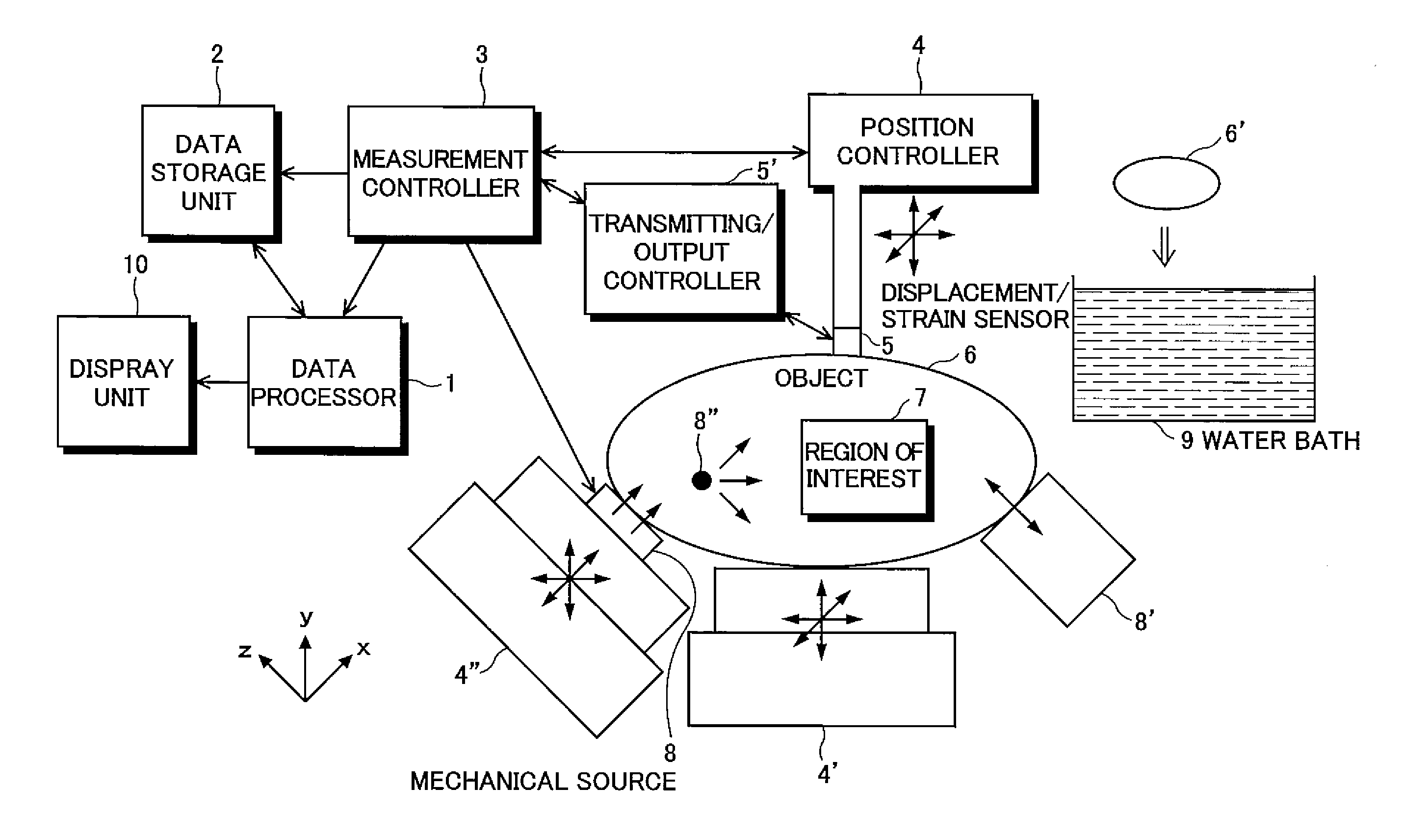
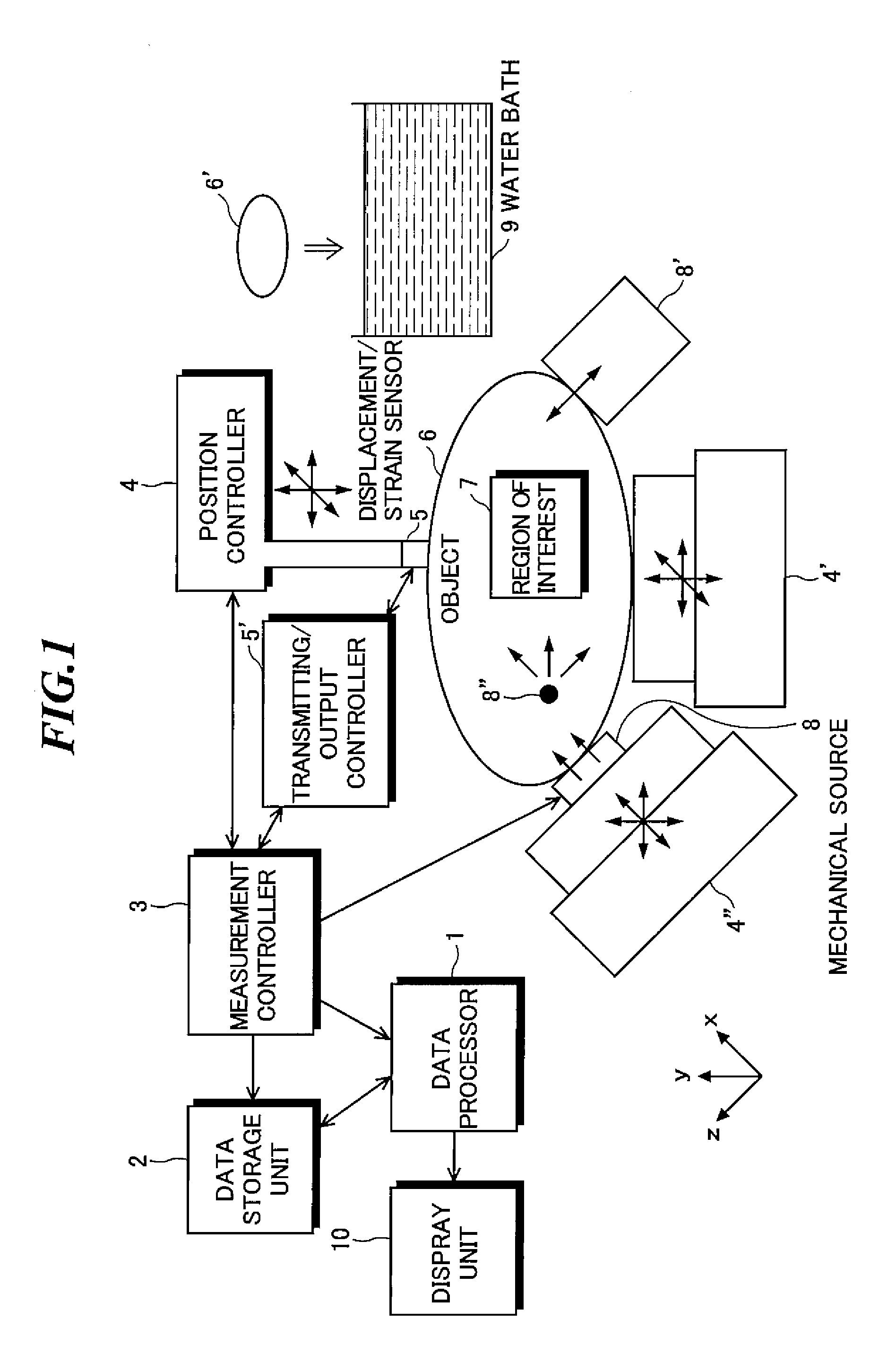
[0109]FIG. 1 shows a schematic representation of a global frame of the imaging and displacement measurement apparatus, related to one of conduct forms of the present invention. This apparatus measures in 3D, 2D or 1D (primarily in the lateral direction) ROI 7 set in the measurement object 6 the displacement vector component (distributions or temporal series), strain tensor component (distributions or temporal series), instantaneous phase change (distribution or temporal series), shear wave propagation speed or propagation direction (distributions or temporal series), shear wave vibration displacement (or velocity or acceleration), shear wave vibration amplitude, shear wave vibration frequency, shear wave vibration direction, shear wave phase (distributions or temporal series), their temporal or spatial partial derivative distributions, etc. to obtain the strain tensor fie...


PUM


Abstract

A displacement measurement method for achieving, at each position of interest, high accuracy measurement of a displacement, a velocity and a strain in an actually generated beam direction by measuring the beam direction angle from ultrasound echo data. The method includes the steps of: generating an ultrasound echo data frame through scanning an object in a lateral direction with an ultrasound steered beam having one steering angle; calculating both a beam direction and a frequency in the beam direction based on an azimuth angle φ=tan−1(fy/fx), a polar angle θ=cos−1[fz/(fx2+fy2+fz2)1/2], and a frequency (fx2+fy2+fz2)1/2 in the case where first spectral moments calculated from local ultrasound echo data at plural different temporal phases are expressed by a three-dimensional frequency vector (fx, fy, fz); and calculating a displacement component in the beam direction at each position of interest generated between plural different temporal phases.

Description

CROSS-REFERENCE TO RELATED APPLICATION[0001]The present application claims priority from Japanese Patent Application No. 2011-134573 filed on Jun. 16, 2011, the contents of which are incorporated herein by reference in their entirety.BACKGROUND OF THE INVENTION[0002]1. Field of the Invention[0003]The present invention is related to the measurement methods and measurement apparatuses for non-invasively and quantitatively measuring internal mechanical properties and physical quantities such as a displacement, a strain, a velocity, an acceleration etc. of target objects, substances, materials, living things etc. For instance, the present invention is related to new measurement methods and measurement apparatuses for generating an internal displacement vector distribution, an internal strain tensor distribution, an internal strain rate tensor distribution, an internal acceleration vector distribution etc. by applying a mechanical source such as a compression, a vibration, a radiated for...

Claims


Application Information

Patent Timeline
IPC IPC(8): A61B8/08A61B8/14
CPCA61B8/08A61B8/483A61B8/485
Inventor SUMI, CHIKAYOSHI
Owner SUMI CHIKAYOSHI
Why Eureka
Try Eureka