High frequency plasma generation system and high frequency plasma ignition device using the same

a plasma generation system and high frequency technology, applied in the direction of electric ignition installation, mechanical equipment, machines/engines, etc., can solve the problems of excessive current flowing, erroneous operation, and pressure rise, so as to reduce high frequency noise, reduce electrode wear, and prevent excessive current flowing

Active Publication Date: 2013-02-28
NIPPON SOKEN +1
View PDF1 Cites 22 Cited by
  • Summary
  • Abstract
  • Description
  • Claims
  • Application Information

AI Technical Summary

Benefits of technology

[0008]It is therefore an object to provide an improved high frequency plasma generation system, which uses dielectric loss for heating fuel, reduces electrode wear by preventing an excessive current f

Problems solved by technology

However, when the pressure in the combustion chamber rises due to abnormal combustion such as detonation (knocking), the pressure rise occurs after an insulating body in a discharge space has been broken by the high voltage supplied from the high voltage power source and the discharge has started.
Thus, high frequency plasma of extremely large energy generates and causes remarkab

Method used


Image

  • High frequency plasma generation system and high frequency plasma ignition device using the same
  • High frequency plasma generation system and high frequency plasma ignition device using the same
  • High frequency plasma generation system and high frequency plasma ignition device using the same

Examples


first embodiment

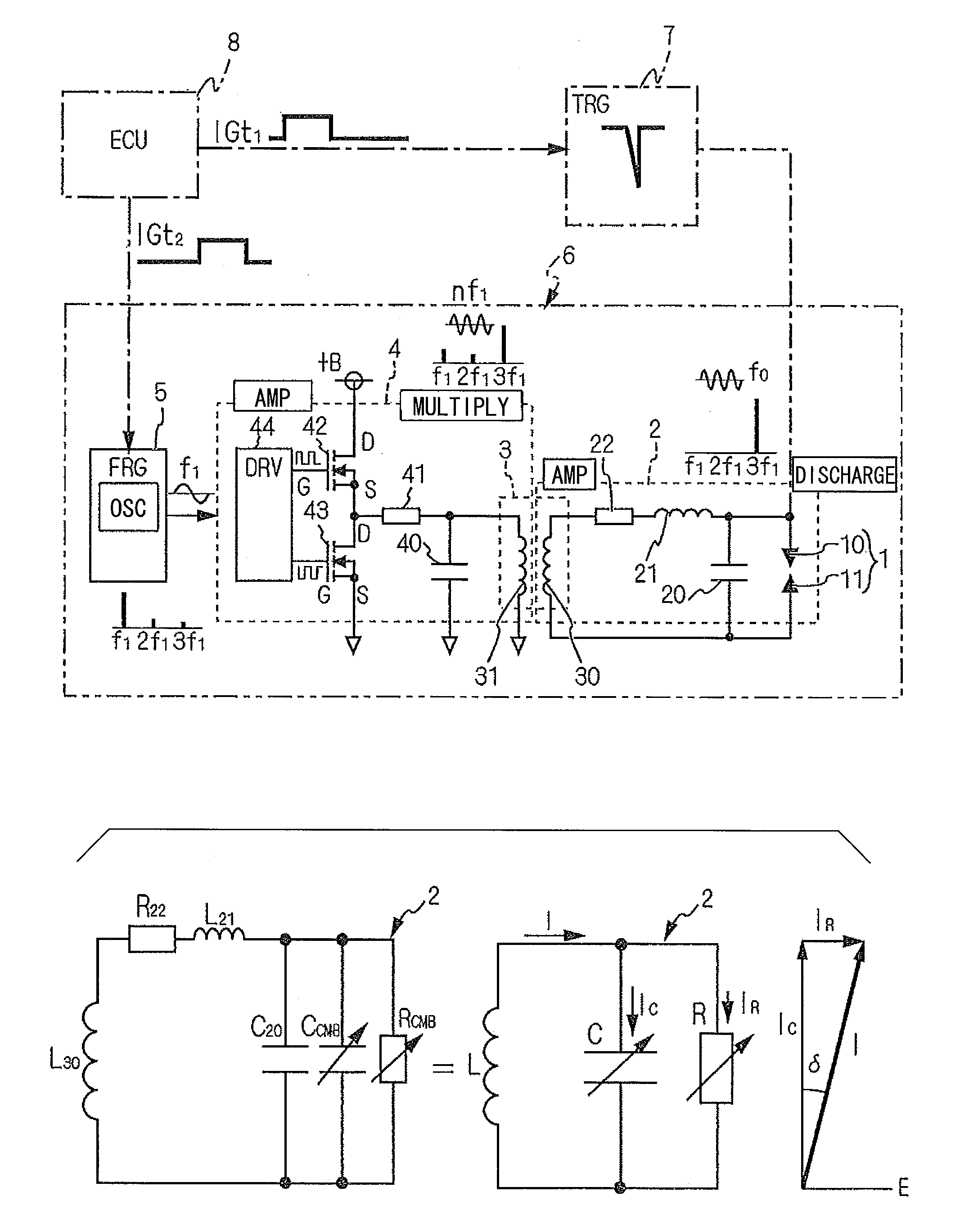
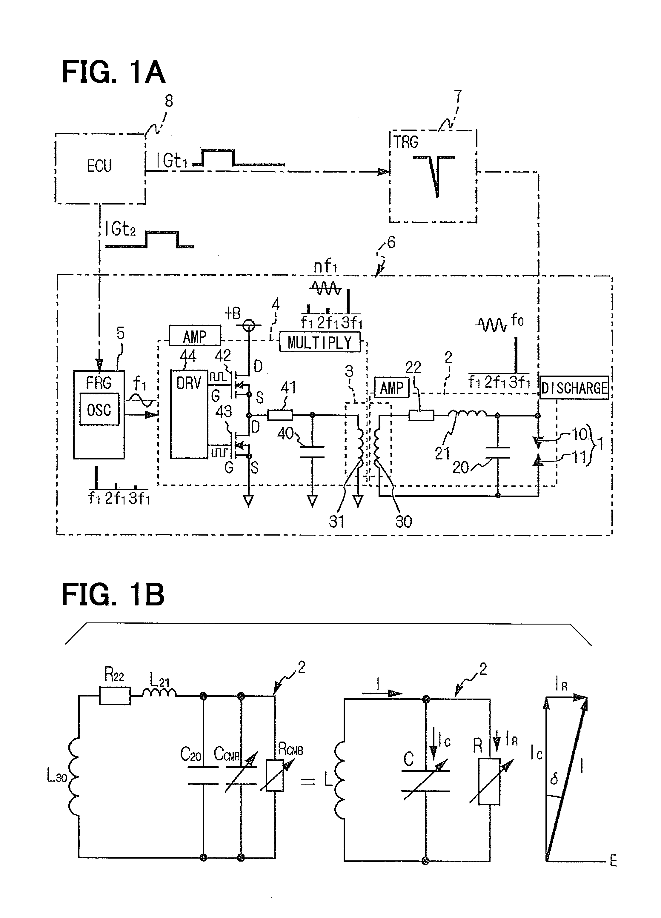
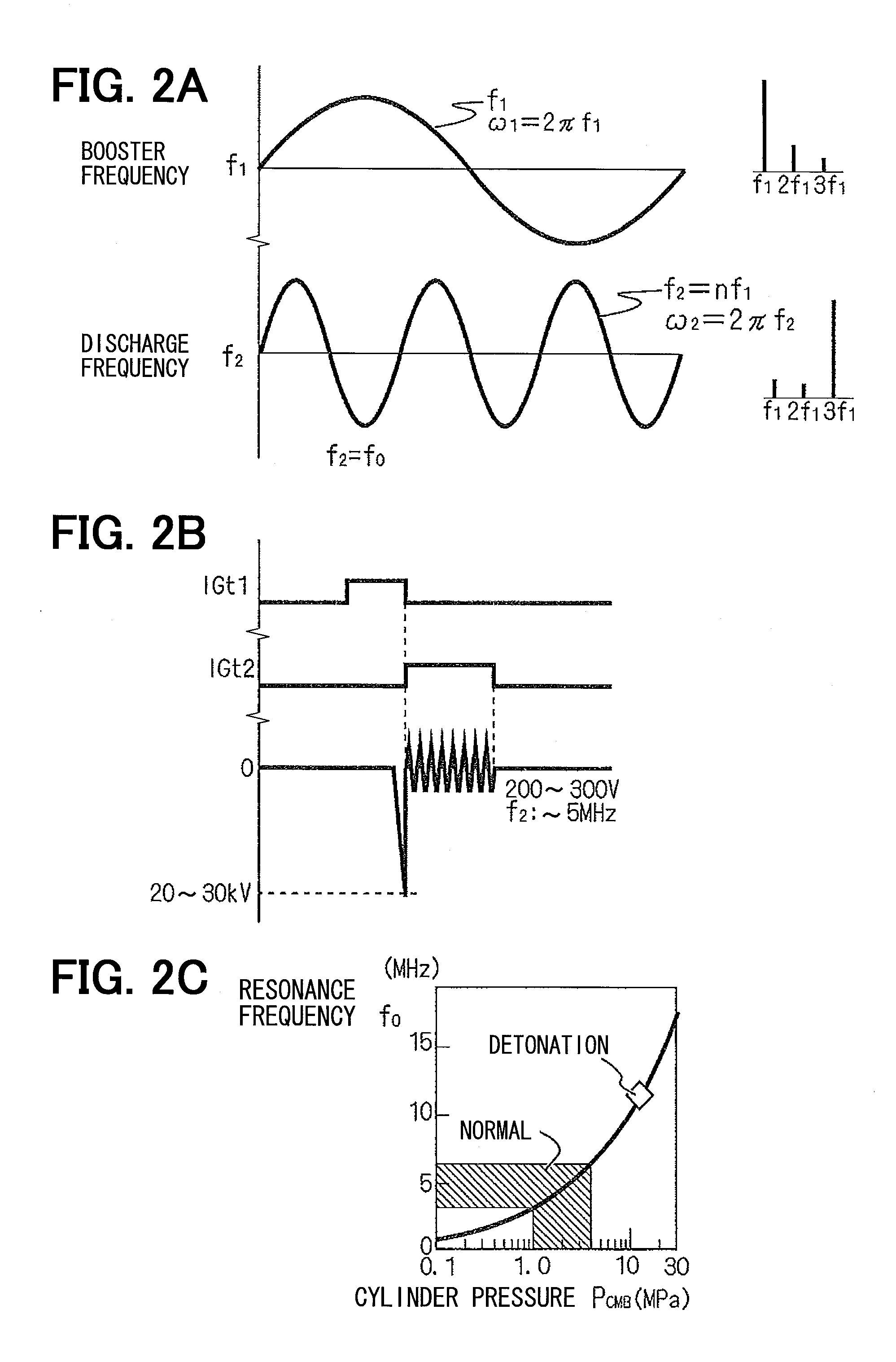
[0023]Referring to FIG. 1, a high frequency plasma generation system is designated by reference numeral 6. The plasma generation system 6 is formed of an ignition plug 1, a discharge circuit 2, a magnetic resonance section 3, a power booster circuit 4 and a frequency generator 5. The magnetic resonance section 3 is provided between the discharge circuit 2 and the power booster circuit 4 as a frequency multiplication section, which outputs a multiplied wave having a frequency corresponding to higher harmonics of an inputted frequency and to integer times (n: two or more) of a fundamental frequency. A resonance frequency f2 of the power booster circuit 4 and a first resonance coil 31 of the magnetic resonance section 3 is set to equal the frequency (n×f1) of the multiplied wave. Further, the resonance frequency f2 is set to equal a resonance frequency f0 of the discharge circuit 2 and a second resonance coil 30 of the magnetic resonance section 3 under a condition that discharge elect...

second embodiment

[0049]A high frequency plasma generation system 6a according to a second embodiment is shown in FIGS. 4A and 4B.

[0050]FIG. 4A is an equivalent circuit diagram showing the plasma generation system 6a according to the second embodiment, and FIG. 4B is also an equivalent circuit diagram of a comparative example, which corresponds to a conventional high frequency plasma generation system 6z. In the comparative example, the same or similar parts as the first embodiment are designated by the same reference numerals and different parts are designated by addition of suffix “z” to reference numerals to clarify difference from the second embodiment.

[0051]Although the class D amplifier circuit is used in the power booster circuit 4 in the first embodiment, a class E amplifier circuit is used in the second embodiment as a power booster circuit 4a, which is more simplified in configuration, as shown in FIG. 4A.

[0052]The power booster circuit 4a has a third resonance coil 45 or a parasitic induct...

third embodiment

[0057]A high frequency plasma generation system 6b according to a third embodiment and a control method executed in the third embodiment will be described with reference to FIGS. 5A, 5B and 6.

[0058]In the third embodiment, the plasma generation system 6b has as a basic structure the plasma generation system 6 or 6a of the first or the second embodiments. In addition, as shown in FIG. 5A, a power booster circuit 4b is provided with a current detector 8, which detects a high frequency current inputted to the first resonance coil 31. The current detector 8 is connected to a feedback control circuit, which includes a high-pass filter (HPF) 90, a peak hold circuit (P / H) 91, an A / D converter 92 and a control microcomputer (CPU) 93. The high-pass filter 90 removes from a detected current ISEN low frequency components generated by deviation of the resonance frequency as shown in FIG. 5B. In addition, a peak hold circuit (P / H) 91 samples and hold a peak of the output of the high-pass filter ...


PUM


Abstract

In a high frequency plasma generation system, a magnetic resonance section is provided as a frequency multiplier section between a discharge circuit and a power booster circuit. The magnetic resonance section extracts from a fundamental wave of a predetermined frequency generated by a frequency generator higher harmonic components, which are multiplied waves of the predetermined frequency and as high as two or more integer times of the fundamental wave. A resonance frequency of the power booster circuit and a first resonance coil is set to be equal to the frequency of the multiplied wave and match to equal a resonance frequency of the discharge circuit and a second resonance coil of the magnetic resonance section when a discharge electrode and a ground electrode are in a predetermined pressure range.

Description

CROSS REFERENCE TO RELATED APPLICATION[0001]This application is based on and incorporates herein by reference Japanese patent applications No. 2011-180378 filed on Aug. 22, 2011 and No. 2011-277347 filed on Dec. 19, 2011.TECHNICAL FIELD[0002]The present disclosure relates to a high frequency plasma generation system, which generates high frequency plasma by application of high frequency current between discharge electrodes. This high frequency plasma generation system is usable in a high frequency plasma ignition device, which discharges high frequency current for ignition of fuel mixture of a low ignitability in a combustion chamber of an internal combustion engine.BACKGROUND ART[0003]It is required recently to improve fuel economy and reduce environmentally harmful substances contained in combustion emissions of an internal combustion engine of a vehicle. For this purpose, an ignition device is required to provide superior ignition performance even in case of lean fuel mixture or ...

Claims


Application Information

Patent Timeline
IPC IPC(8): H05H1/50
CPCH05H1/46H05H2242/1005F02P23/045F02P9/007F02P3/005F02P3/01H05H2242/22
Inventor SUGINO, MASAYOSHIFUKATSU, KAZUKITOMITA, YOSHITAKASHIBATA, MASAMICHIABE, YUYA
Owner NIPPON SOKEN
Why Eureka
Try Eureka