Exhaust gas purification system for internal combustion engine

a technology for exhaust gas purification and internal combustion engines, which is applied in the direction of machines/engines, mechanical equipment, separation processes, etc., can solve the problems of reducing the ease of installation of the exhaust gas purification system in the vehicle, increasing manufacturing costs, and reducing flexibility, so as to reduce nitrogen oxides, increase flexibility in layout, and reduce the effect of deterioration of performan

Inactive Publication Date: 2013-03-07
TOYOTA JIDOSHA KK
View PDF9 Cites 3 Cited by
  • Summary
  • Abstract
  • Description
  • Claims
  • Application Information

AI Technical Summary

Benefits of technology

[0032]The present invention can increase the flexibility in the layout of an exhaust gas purification system for an internal combustion engine including an SCR system, without a deterioration of the performance in reducing nitrogen oxides (NOx).

Problems solved by technology

However, this can lead to a decrease in the ease of installation of the exhaust gas purification system in a vehicle and / or an increase in the manufacturing cost due to a decrease in the flexibility in the layout of the exhaust gas purification system.

Method used


Image

  • Exhaust gas purification system for internal combustion engine
  • Exhaust gas purification system for internal combustion engine
  • Exhaust gas purification system for internal combustion engine

Examples


embodiment 1

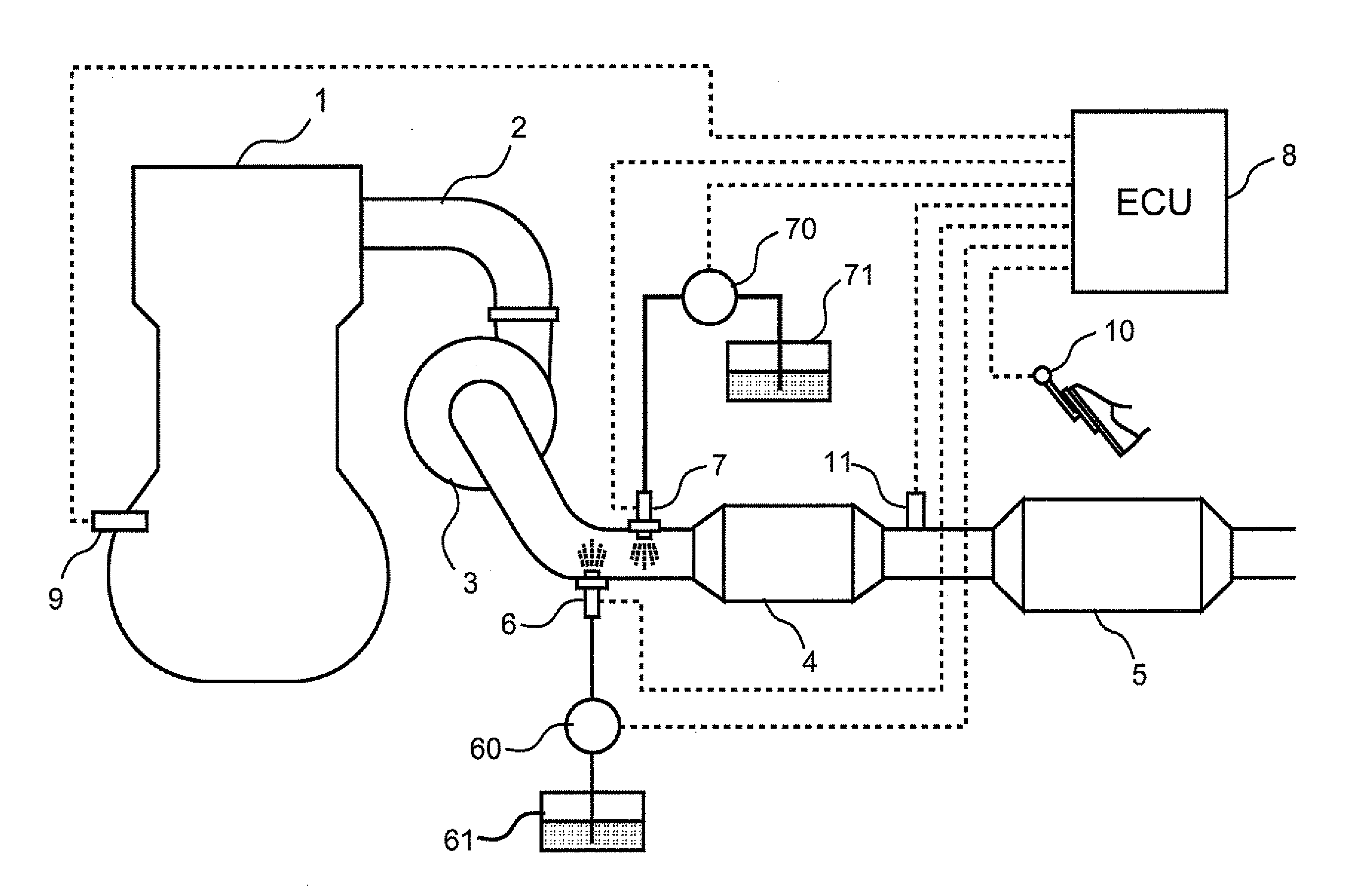
[0039]A first embodiment of the present invention will first be described with reference to FIGS. 1 to 4. FIG. 1 is a diagram showing the general configuration of an exhaust system of an internal combustion engine to which the present invention is applied. While the internal combustion engine 1 shown in FIG. 1 is a compression ignition internal combustion engine (diesel engine), the engine may be a spark ignition internal combustion engine (gasoline engine).

[0040]In FIG. 1, the internal combustion engine 1 is connected with an exhaust passage 2. The exhaust passage 2 is a passage through which gas (exhaust gas) flowing out of the cylinders of the internal combustion engine 1 is to flow. In the middle of the exhaust passage 2, a turbine 3 of a centrifugal supercharger (or turbocharger) is provided. An exhaust gas purification apparatus 4 is provided in the exhaust passage 2 downstream of the turbine 3.

[0041]The exhaust gas purification apparatus 4 has a cylindrical casing which house...

embodiment 2

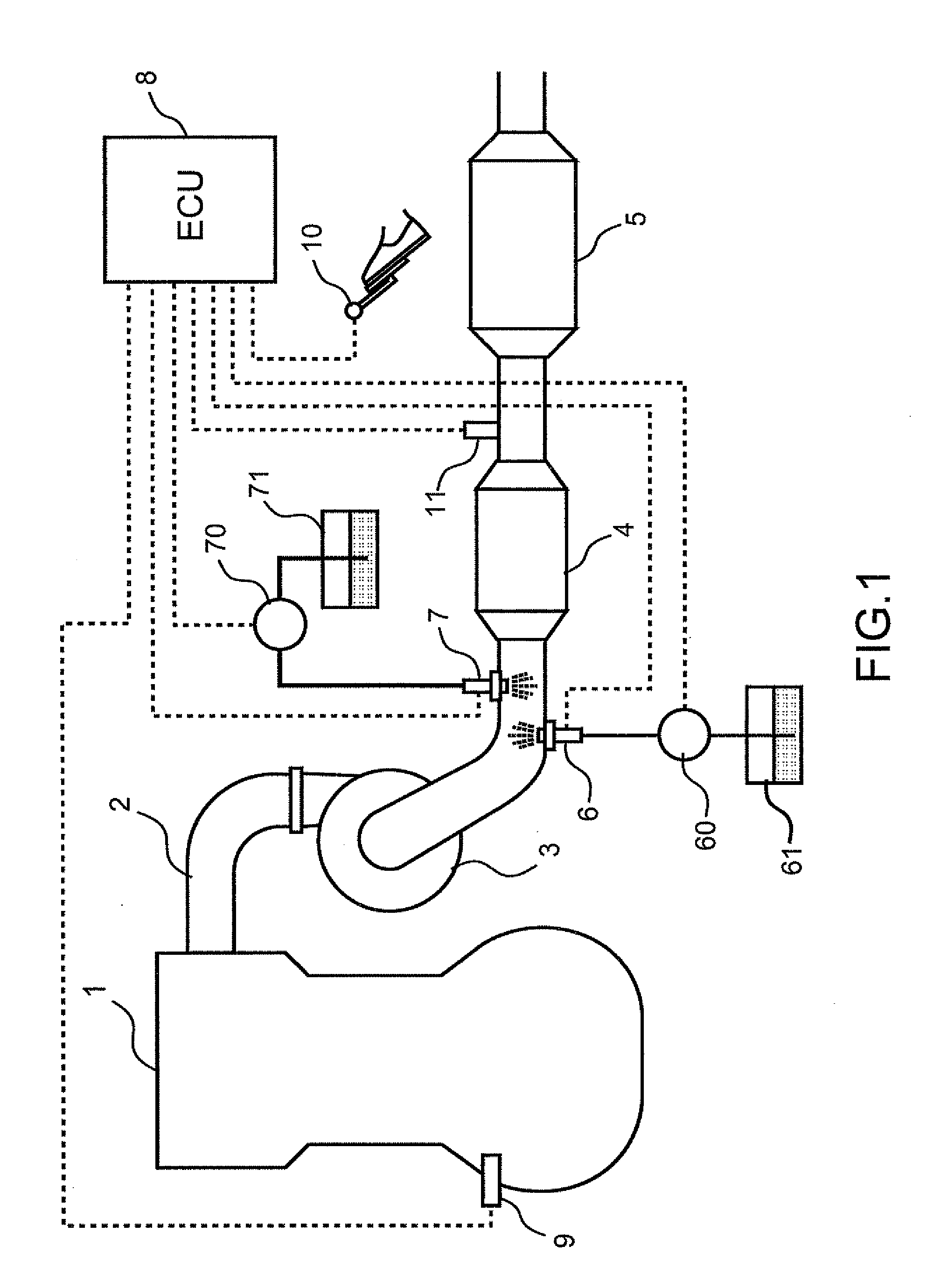
[0081]A second embodiment of the present invention will be described with reference to FIG. 5. In the following, features different from those in the above-described first embodiment will be described, and like features will not be described.

[0082]What is different in this embodiment from the above-described first embodiment is that a burner 12 is additionally provided in the exhaust passage 2 between the turbine 3 and the exhaust gas purification apparatus 4. The burner 12 is a device that burns secondary air supplied from an air pump 120 and fuel supplied from the first pump 60.

[0083]The burner is equipped with an ignition plug that is not shown in the drawing and adapted to burn secondary air and fuel with the operation of the ignition plug. The gas burned in the burner 12 (burned gas) is introduced into the exhaust passage 2 through a discharge pipe 121. Although in the case shown in FIG. 5, the burner 12 and the fuel addition valve 6 use the first pump 60 in common, a dedicated...


PUM

PropertyMeasurementUnit
temperatureaaaaaaaaaa
timeaaaaaaaaaa
temperatureaaaaaaaaaa

Abstract

An object of the present invention is to increase the flexibility in the layout of an exhaust gas purification system for an internal combustion engine including selective catalytic reduction catalyst provided in an exhaust passage of the internal combustion engine and an addition device for supplying reducing agent derived from ammonia to the selective catalytic reduction catalyst, without a deterioration of the performance in reducing nitrogen oxides. To achieve the object, the exhaust gas purification system for an internal combustion engine according to the present invention is configured to supply hydrocarbon at the same time when reducing agent derived from ammonia is supplied to the selective catalytic reduction catalyst, thereby producing reducing agent that is hard to be oxidized by a precious metal catalyst.

Description

TECHNICAL FIELD[0001]The present invention relates to an exhaust gas purification system for an internal combustion engine, in particular to an exhaust gas purification system equipped with a catalyst that reduces nitrogen oxides (NOx) in the exhaust gas with supply of ammonia.BACKGROUND ART[0002]There has been known an SCR (Selective Catalytic Reduction) system equipped with a selective catalytic reduction catalyst provided in an exhaust passage of an internal combustion engine and a reducing agent addition valve provided in the exhaust passage upstream of the selective catalytic reduction catalyst, in which a compound or composition derived from ammonia is added through the aforementioned reducing agent addition valve.[0003]With increasingly strict exhaust emission control, there arises a need for adding an oxidation catalyst and / or particulate filter to SCR systems. Thus, systems equipped with a fuel addition valve, an oxidation catalyst, a particulate filter, a urea addition val...

Claims


Application Information

Patent Timeline
Patent Type & Authority Applications(United States)
IPC IPC(8): F01N3/10
CPCF01N3/208F01N2610/02F01N2610/03Y02T10/24F01N3/2033F01N2560/06B01D2251/2062F01N2900/1602Y02T10/26F01N13/009B01D53/90B01D53/9409B01D53/9495F01N2900/0416Y02T10/12
Inventor TOSHIOKA, SHUNSUKEHIROTA, SHINYAITOH, KAZUHIROFUKUDA, KOICHIROMIKAMI, AKIRA
Owner TOYOTA JIDOSHA KK
Why Eureka
Try Eureka