Apparatus and method for the synthesis and treatment of metal monolayer electrocatalyst particles in batch or continuous fashion

Inactive Publication Date: 2013-03-07
BROOKHAVEN SCI ASSOCS
View PDF3 Cites 7 Cited by
  • Summary
  • Abstract
  • Description
  • Claims
  • Application Information

AI Technical Summary

Benefits of technology

[0016]The apparatus and method disclosed in this specification provide atomic-level control over film growth on a large number of particles, thereby making it suitable for commercial appli

Problems solved by technology

Although noble metals have been shown to be some of the best electrocatalysts, their successful implementation in commercially available energy conversion devices is hindered by their high cost in c

Method used


Image

  • Apparatus and method for the synthesis and treatment of metal monolayer electrocatalyst particles in batch or continuous fashion
  • Apparatus and method for the synthesis and treatment of metal monolayer electrocatalyst particles in batch or continuous fashion
  • Apparatus and method for the synthesis and treatment of metal monolayer electrocatalyst particles in batch or continuous fashion

Examples


example 1

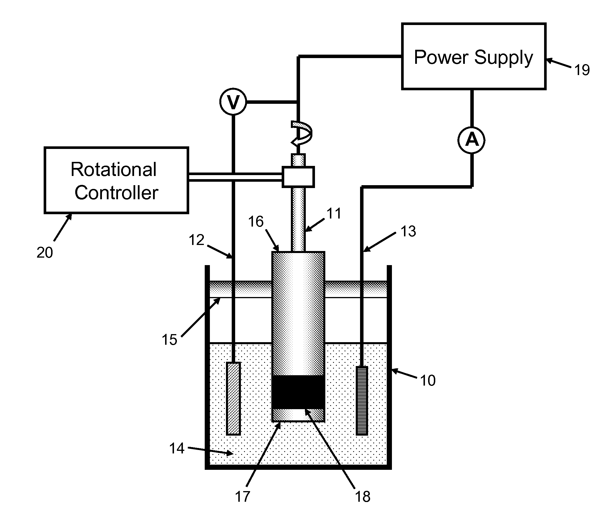
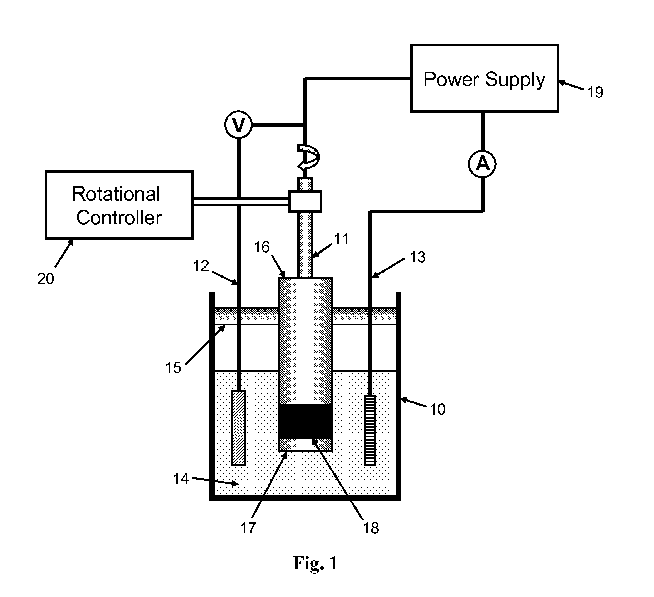
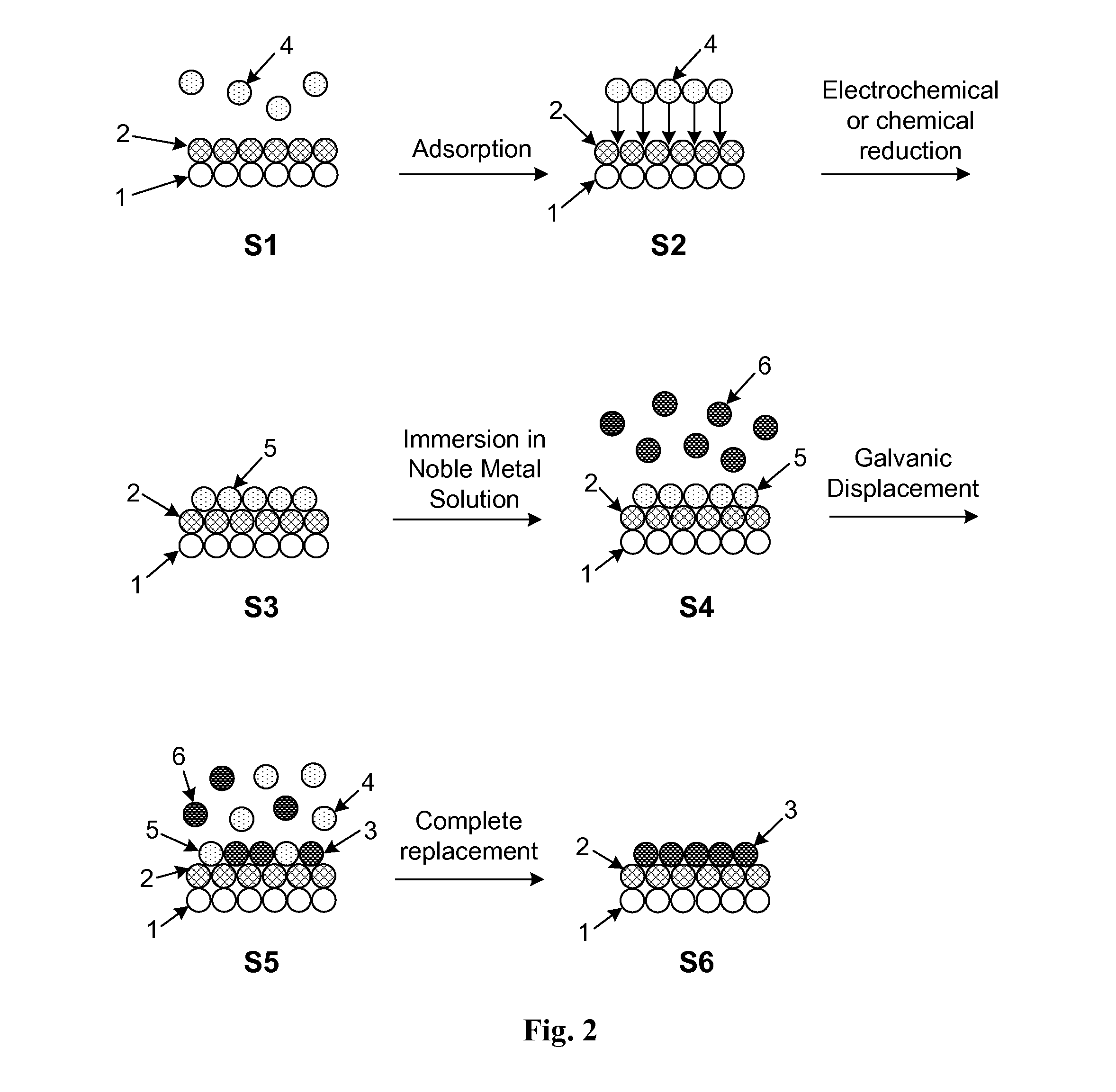
[0067]The present invention may be illustrated by way of exemplary embodiments. In this example, the deposition process will be described with reference to deposition onto non-noble metal-noble metal core-shell nanoparticles. The core-shell nanoparticles may be initially formed using any method known in the art including, for example, those disclosed in U.S. patent application Ser. No. 12 / 709,910. The deposition process in Example 1 will now be described using FIGS. 2 and 3 as a reference. The nanoparticle surface in FIG. 2 shows a portion of the non-noble metal core (1) along with the noble metal shell (2). Non-noble metal ions (4) are initially adsorbed on the surface by immersing the nanoparticles in a cell (10) comprising the appropriate concentration of non-noble metal ions (4) in step S1. The non-noble metal ions (4) are contained in solution within the slurry (14) illustrated in FIG. 1. Typical non-noble metal ions that may be used for UPD of an initial adlayer include, but a...

example 2

[0072]A second exemplary embodiment of the present invention will now be described in detail with reference to FIG. 4 which shows the overall process flow for film growth by UPD and galvanic displacement using a rotating cylinder slurry cell. Initially, in step S10, particles of the desired composition, size, and shape are formed. Such particles may also be purchased from commercial vendors, such as E-TEK (39 Veronica Av., Somerset, N.J., 08873) and BASF (Germany). The particles used may be of any type onto which atomic layers of the desired material may be deposited. In a preferred embodiment the particles are of the type described in Section I above. Prior to deposition of an initial adlayer by UPD, it is necessary to prepare a slurry comprising the particles and ions of the desired UPD element as shown in step S11. The UPD element must be a material which exhibits underpotential deposition such as, for example, any of Cu, Pb, Bi, Sn, Ce, Ag, Sb, and Tl.

[0073]In step S12 the elect...


PUM

PropertyMeasurementUnit
Massaaaaaaaaaa
Volumeaaaaaaaaaa
Volumeaaaaaaaaaa

Abstract

An apparatus and method for the synthesis and treatment of electrocatalyst particles in batch or continuous fashion is provided. In one embodiment, the apparatus is comprised of a three-electrode cell which includes a reference electrode, a counter electrode, and a working electrode. The working electrode is preferably a cylindrical vessel having an electrically conductive region. The electrode assembly is introduced into a slurry containing metal ions and a plurality of particles. During operation an electrical potential is applied and the working electrode is rotated at a predetermined speed. When particles in the slurry collide with the electrically conductive region the transferred charge facilitates deposition of an ad-layer of the desired metal. In this manner film growth can commence on a large number of particles simultaneously. This process is especially suitable as a commercial thin film deposition process for forming catalytically active layers on nanoparticles for use in energy conversion devices.

Description

[0001]This application is an International PCT application, which claims the benefit of U.S. Provisional Application No. 61 / 316,874, filed on Mar. 24, 2010 which is hereby incorporated by reference in its entirety.[0002]This invention was made with Government support under contract number DE-AC02-98CH10886, awarded by the U.S. Department of Energy. The Government has certain rights in the invention.BACKGROUND[0003]I. FIELD OF THE INVENTION[0004]This invention relates generally to the controlled deposition of ultrathin films. In particular, the present invention relates to an apparatus and method for depositing atomic submonolayer to multilayer thin films on a plurality of particles in batch or continuous fashion. The present invention also relates to nanoparticle electrocatalysts having ultrathin catalytically active layers formed using the disclosed apparatus and method.[0005]II. BACKGROUND OF THE RELATED ART[0006]Metals such as platinum (Pt), palladium (Pd), ruthenium (Ru), and re...

Claims


Application Information

Patent Timeline
IPC IPC(8): C25D7/00C25D5/04C25D17/16
CPCC25D17/12C25D21/12C25D21/10C25D5/08C25D15/00C23C18/54C25D7/006Y02E60/50C25D17/10H01M4/8853
Inventor ADZIC, RADOSLAVVUKMIROVIC, MIOMIR
Owner BROOKHAVEN SCI ASSOCS
Why Eureka
Try Eureka