In-situ combustion recovery process using single horizontal well to produce oil and combustion gases to surface

a recovery process and combustion gas technology, applied in the direction of machines/engines, mechanical equipment, borehole/well accessories, etc., can solve the problems of reducing process efficiency, wasting energy, and reducing the symmetry of simultaneously proceeding in mutually opposite directions, so as to achieve rapid oil collection

Inactive Publication Date: 2013-03-28
ARCHON TECH LTD
View PDF4 Cites 5 Cited by
  • Summary
  • Abstract
  • Description
  • Claims
  • Application Information

AI Technical Summary

Benefits of technology

[0029]Specifically, with regard to advantage (ii) above, by situating a vertical injection well proximate the midsection of a horizontal well and by propagating the combustion front in two mutually opposite directions along such well bore, such allows more rapid collection of oil than by the method disclosed in either U.S. Pat. No. 5,626,191 (“toe to heel” propagation of combustion front) or U.S. Pat. No. 7,493,952 (“heel to toe” propagation of combustion front) which merely causes the combustion front to advance in a single direction along the horizontal well bore.
[0030]Moreover, by injecting an oxygen-containing gas at less than fracturing pressure through the injection well and establishing a zone of oxygen-containing gas around the injection well that extends upwards to the reservoir cap rock and downward (but not reaching) the horizontal production well, and establishing a water, oil and combustion gas drainage front that grows along the horizontal well in directions both towards the toe and towards the heel of the horizontal well and also grows perpendicularly to the strike of the horizontal well, the heated oil and water and the heated combustion gas may all drain under the influence of gravity and pressure forces and further be collected in the horizontal well free of oxygen or oxidizing gas, which greatly reduces the chance of explosion. Compared with the process of vent gas withdrawal by separate vent wells, the present process preserves the valuable flammable components for production to the surface rather than burning them in the reservoir where the heat is wasted, and it utilizes some of the generated hydrogen to hydrocrack the hot oil, thus producing a stable partially upgraded oil.

Problems solved by technology

In processes with gas vent wells, these gases are combusted in the upper reaches of the reservoir and must be cooled to protect the vent wells from thermal damage, so that the energy is wasted.
Notably, if the inner diameter of the horizontal leg of the producer well is too small, then wellbore hydraulics interfere with the symmetry of combustion front advancement-the front advancement in the direction of the heel of the horizontal producer will be faster than toward the toe, thereby reducing efficiency of the process, and the symmetry of simultaneously proceeding equally in mutually opposite directions along the horizontal producer will be lost, and more importantly slowed in the direction progressing towards the toe.

Method used


Image

  • In-situ combustion recovery process using single horizontal well to produce oil and combustion gases to surface
  • In-situ combustion recovery process using single horizontal well to produce oil and combustion gases to surface
  • In-situ combustion recovery process using single horizontal well to produce oil and combustion gases to surface

Examples


example 1

[0091]Table 1 below gives a list of list of Numerical Model Parameters used in this Example.

[0092]Numerical simulator: STARS™ 2009.1, Computer Modelling Group Limited

Model Dimensions:

[0093]Length: 540 meters, 216 grid blocks at 2.5 meters each

[0094]Width: 50 m, 20 grid blocks of 2.5 meters each with an element of symmetry, giving a wellbore spacing of 100 m

[0095]Height: 20 m, 20 grid blocks of 1-meter each

Horizontal Production Well

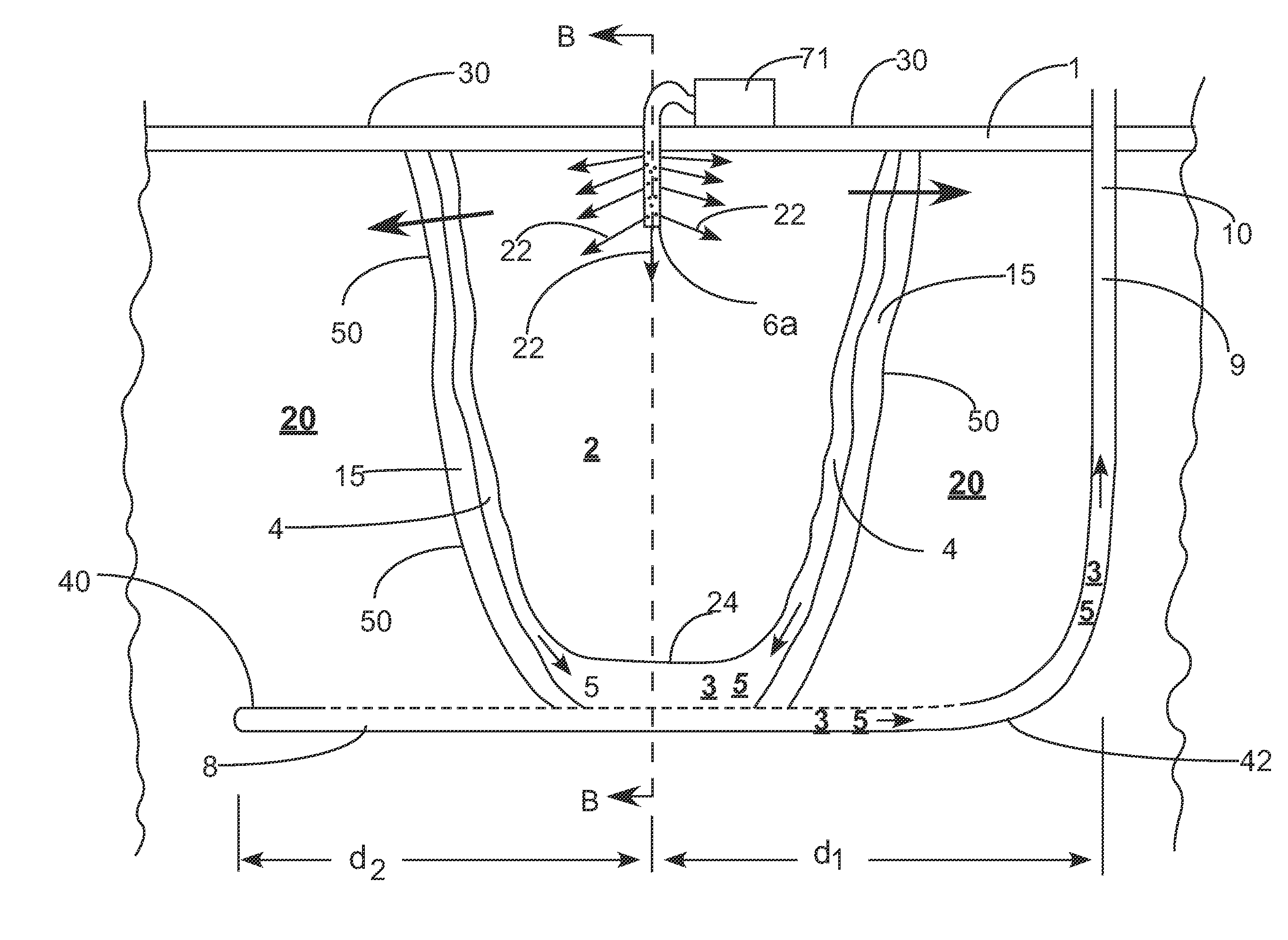
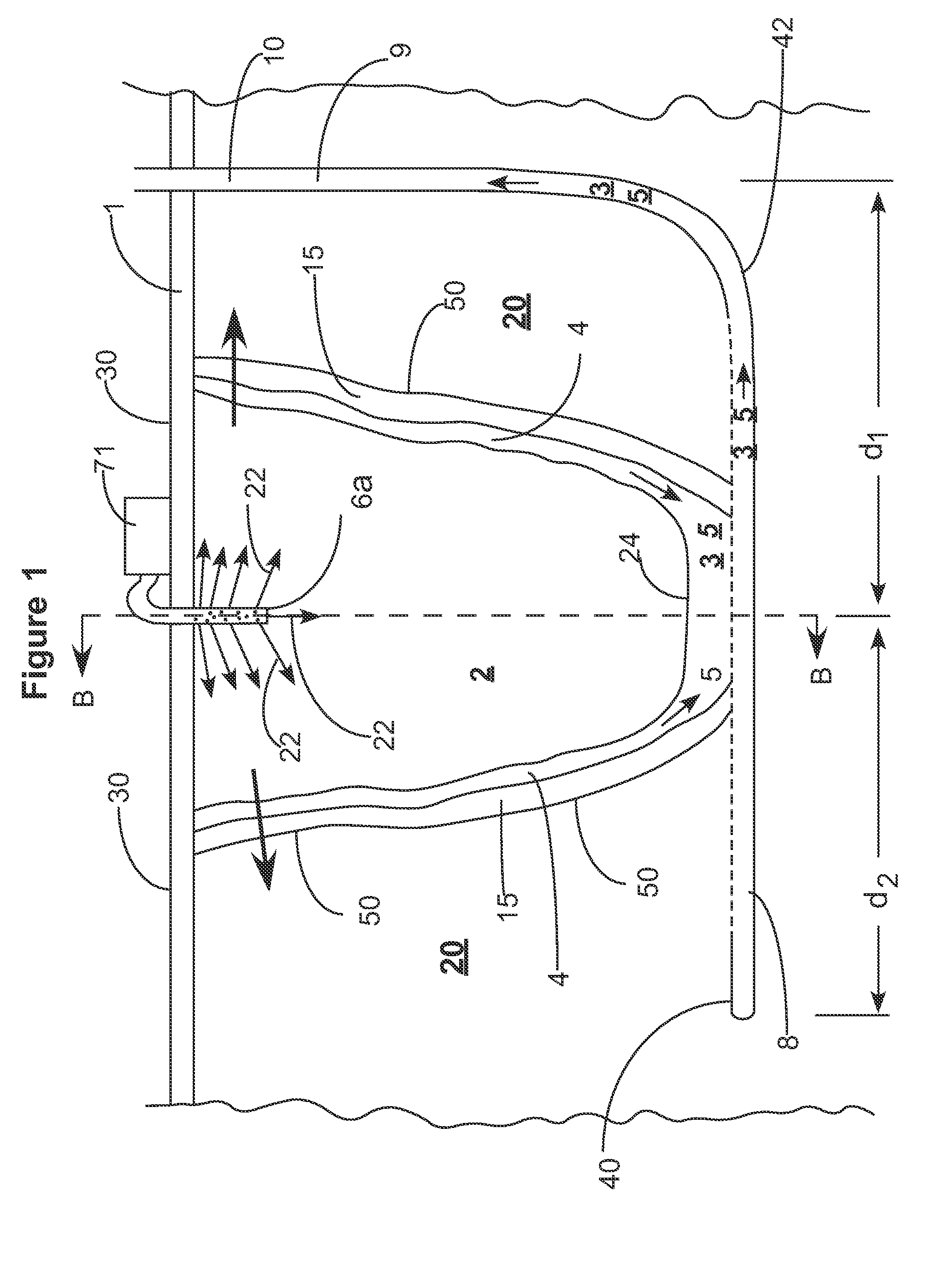
[0096]A discrete horizontal wellbore of 500 m extended from grid blocks 9 to 208, leaving a 20-meter buffer zone on either end of the horizontal well. The inner diameter of the horizontal leg was 9⅝ inches. A steam rate in the horizontal well tubing of 10 m3 / d (water equivalent) was maintained throughout all the tests, although this procedure is optional.

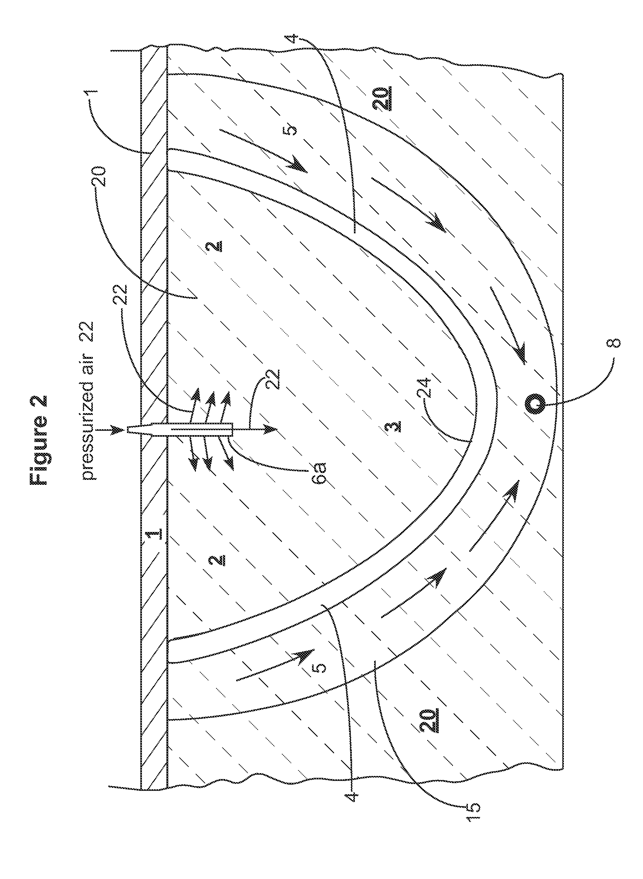
Steam and Oxidizing Gas Injector(s)

[0097]A number of models were run having from 1-5-vertical injectors placed over the horizontal producer and perforated in grid blocks 6-9 for steam pre-heating (for 3-mo...


PUM


Abstract

An in-situ combustion process which process does not employ one or more separate gas venting wells. At least one vertical production well having a substantially vertical portion extending downwardly into the reservoir and a horizontal leg portion extending horizontally outwardly therefrom completed relatively low in the reservoir is provided. At least one vertical oxidizing gas injection well, positioned above and in spaced relation to the horizontal well, is positioned laterally along the horizontal well approximately midsection thereof. Oxidizing gas is injected therein and combustion fronts are caused to progress outwardly from such injection well in mutually opposite directions along the horizontal well. Preferably a plurality of injection wells are provided along the direction of the horizontal well, and oxidizing gas is injected in each and combustion fronts caused to progress outwardly and in opposite directions from each, and oil is caused to drain down into the horizontal well, which oil along with hot combustion gases is produced to surface.

Description

FIELD OF THE INVENTION[0001]This invention relates to a process for recovering viscous hydrocarbons from a subterranean reservoir using in-situ combustion, a vertical oxidizing gas injection well, and a separate horizontal well, and in particular to an improved process which does not employ separate additional gas venting wells.BACKGROUND OF THE INVENTION[0002]In situ combustion processes for producing oil from viscous underground hydrocarbon formations and various methods for separating hydrocarbons from subterranean formations containing hydrocarbons are well known in the art.[0003]By way of example, U.S. Pat. No. 3,502,372 (M. Prats) discloses a process wherein shale oil and soluble aluminum compounds are recovered from a rubbleized or fragmented shale oil formation by top-down burning of the shale oil. The removal of oil is conducted to clean the shale for subsequent solution mining of the aluminum in the shale with alkaline chemicals. The pyrolyzing agent can be a hot mixture o...

Claims


Application Information

Patent Timeline
Patent Type & Authority Applications(United States)
IPC IPC(8): E21B43/243
CPCE21B43/305E21B43/243
Inventor AYASSE, CONRAD
Owner ARCHON TECH LTD
Why Eureka
Try Eureka