Fuel Heating in Combined Cycle Turbomachinery
- Summary
- Abstract
- Description
- Claims
- Application Information
AI Technical Summary
Benefits of technology
Problems solved by technology
Method used
Image
Examples
Embodiment Construction
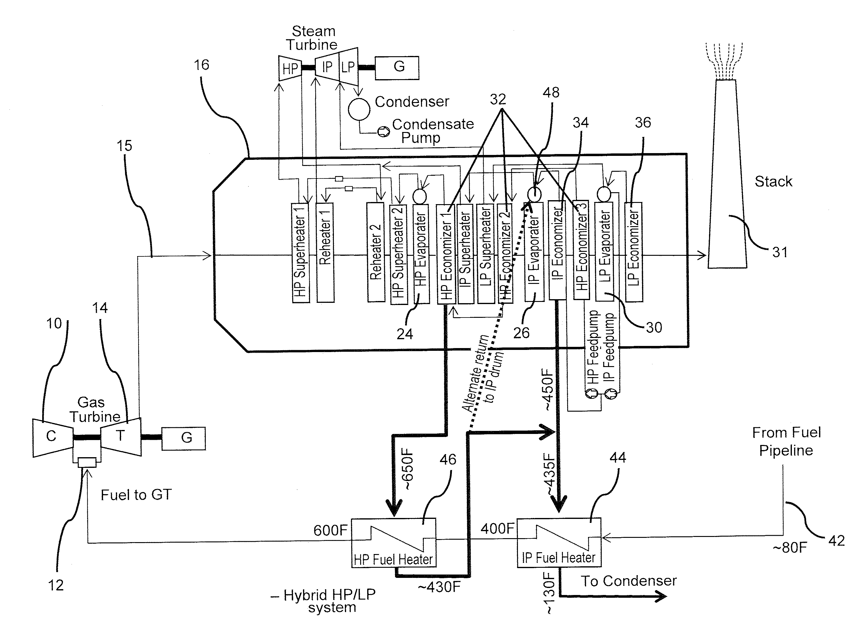
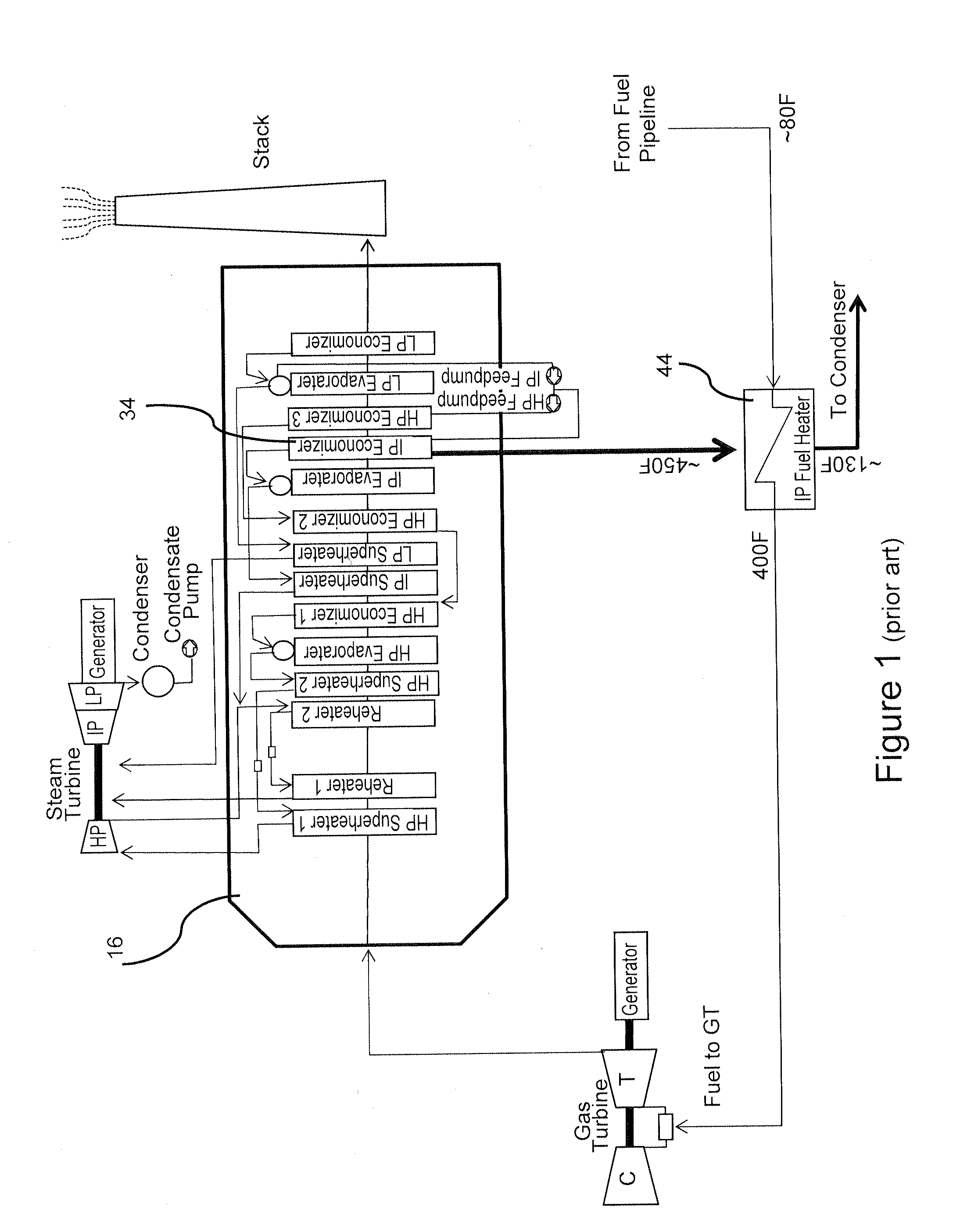
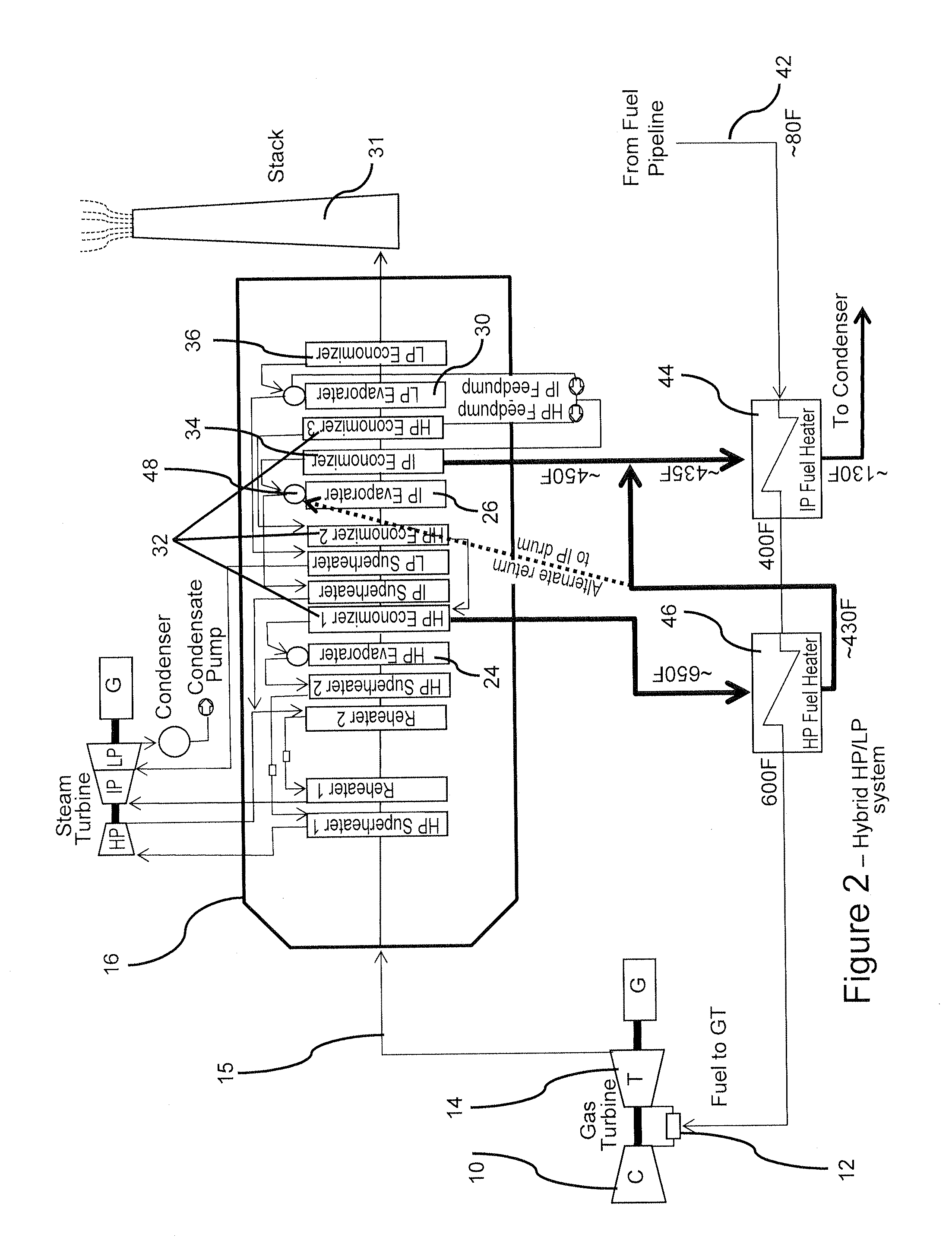
[0012]FIG. 2 illustrates a schematic flow diagram of a three-pressure combined cycle turbomachine. The machine includes a compressor 10, a combustor 12, and a turbine powered by expanding hot gases produced in the combustor 12 for driving an electrical generator G. Exhaust gases from the gas turbine 14 are supplied through conduit 15 to a heat recovery steam generator (HRSG) 16 for recovering waste heat from the exhaust gases. The HRSG includes high pressure (HP), intermediate pressure (IP), and low pressure (LP) sections. Each of the HP, IP, and LP sections includes an evaporator section 24, 26, 30, respectively, and an economizer section 32, 34, 36, respectively, for pre-heating water before it is converted to steam in the respective evaporator section. Water is fed to the HRSG 16 to generate steam. Heat recovered from the exhaust gases supplied to the HRSG 16 is transferred to water / steam in the HRSG 16 for producing steam which is supplied to a steam turbine ST for driving a gen...
PUM
 Abstract
Description
Claims
Application Information
 - R&D
- Intellectual Property
- Life Sciences
- Materials
- Tech Scout
- Unparalleled Data Quality
- Higher Quality Content
- 60% Fewer Hallucinations
Browse by: Latest US Patents, China's latest patents, Technical Efficacy Thesaurus, Application Domain, Technology Topic, Popular Technical Reports.
© 2025 PatSnap. All rights reserved.Legal|Privacy policy|Modern Slavery Act Transparency Statement|Sitemap|About US| Contact US: help@patsnap.com


