
Ink for printing a mobile phone antenna pattern, method for manufacturing a synthetic resin part for a mobile phone on which an antenna pattern is printed using the ink, and synthetic resin part for a mobile phone on which an antenna pattern is printed

Inactive Publication Date: 2013-03-28
YEN AN TECH +1
View PDF11 Cites 14 Cited by
  • Summary
  • Abstract
  • Description
  • Claims
  • Application Information

AI Technical Summary

Benefits of technology

This patent provides an ink and method for printing an antenna pattern on a mobile phone without using plating, which increases production efficiency and reduces pollution. Additionally, this patent also provides a plastic part with a printed antenna pattern for a mobile phone.

Problems solved by technology

However, this method may result in defects, such as the metal piece becoming partially separated from the resin body due to uneven adhesion across the pattern, and there may also be difficulties in maintaining important properties, such as for wireless communication or electromagnetic shielding, for extended periods of time.
However, this method entails a somewhat complicated process and does not ensure stable properties.
However, existing methods of forming an antenna pattern, by printing a pattern with ink onto a plastic surface and performing plating over the pattern, entail complicated processes and necessarily include plating processes, so that the reduced yield resulting from the plating process causes lower productivity.
Moreover, plating processes are detrimental to the environment in most cases, and hence entail problems of polluting the environment and imposing health risks for workers participating in the processes.

Method used


Image

  • Ink for printing a mobile phone antenna pattern, method for manufacturing a synthetic resin part for a mobile phone on which an antenna pattern is printed using the ink, and synthetic resin part for a mobile phone on which an antenna pattern is printed
  • Ink for printing a mobile phone antenna pattern, method for manufacturing a synthetic resin part for a mobile phone on which an antenna pattern is printed using the ink, and synthetic resin part for a mobile phone on which an antenna pattern is printed
  • Ink for printing a mobile phone antenna pattern, method for manufacturing a synthetic resin part for a mobile phone on which an antenna pattern is printed using the ink, and synthetic resin part for a mobile phone on which an antenna pattern is printed

Examples


Embodiment Construction

[0028]An embodiment of the present invention will be described below in more detail with reference to the accompanying drawings.

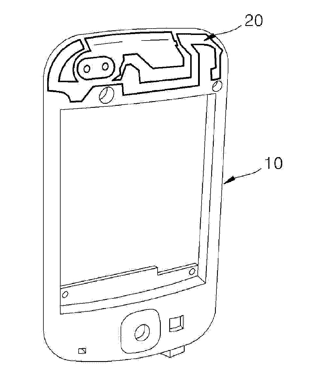
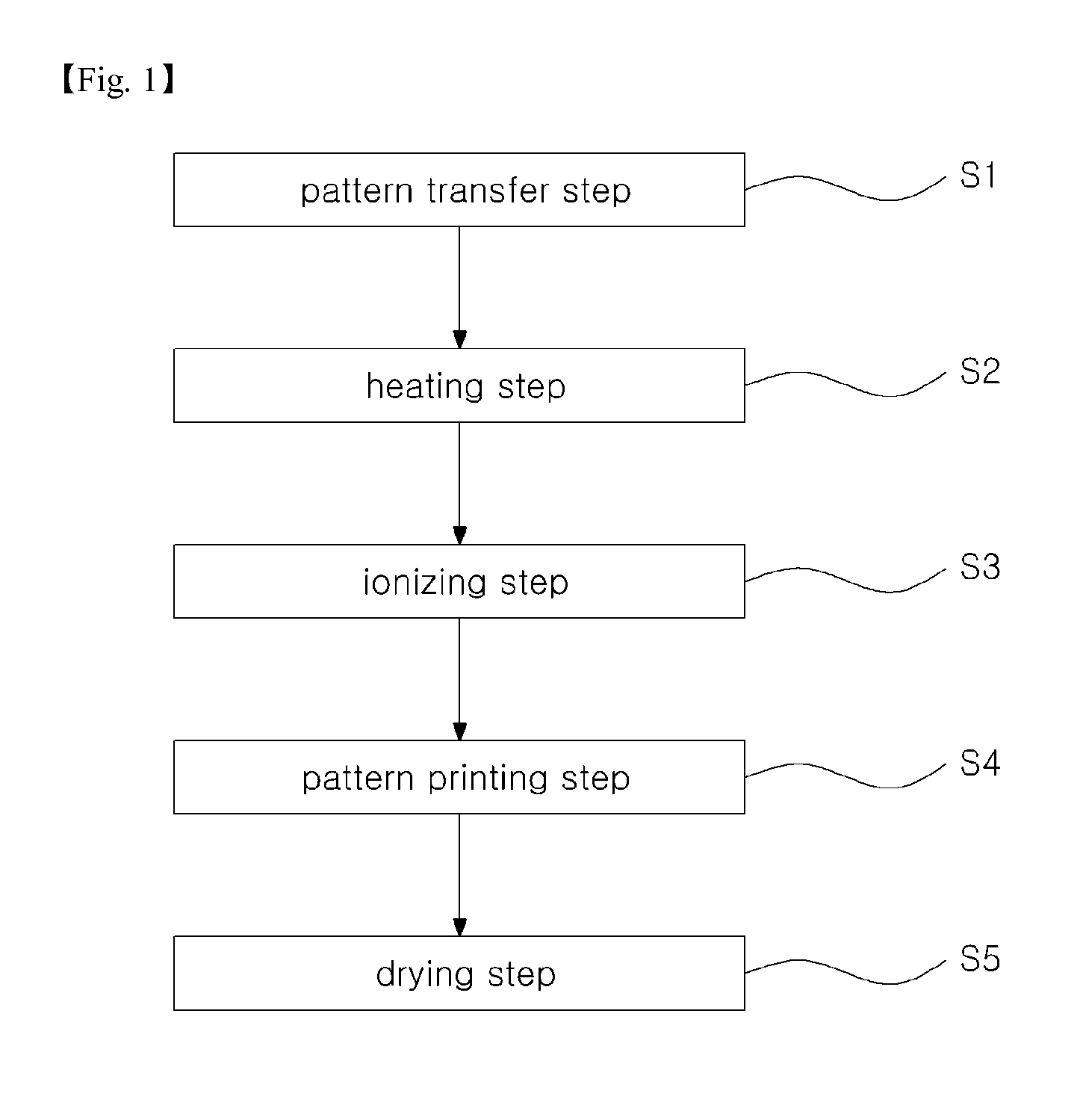
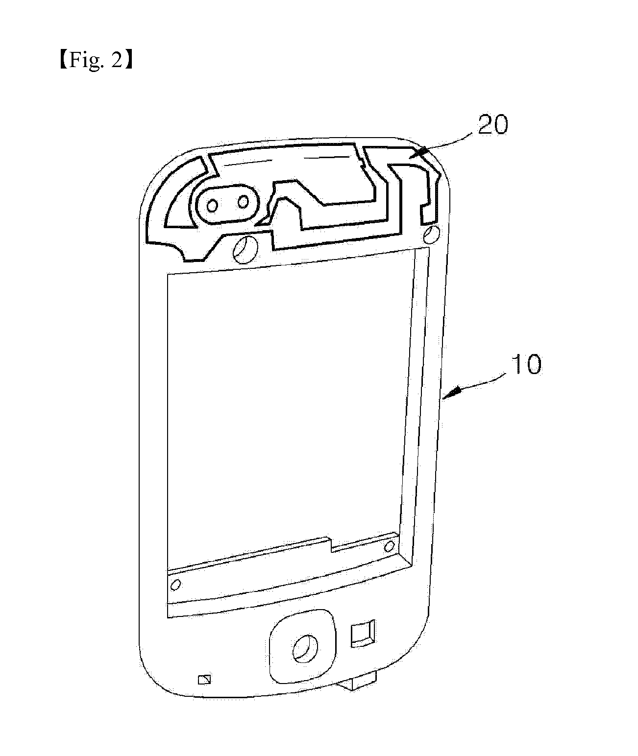
[0029]FIG. 1 is a process diagram illustrating a method of manufacturing a part for a mobile phone on which the antenna pattern is printed with ink according to an embodiment of the present invention. FIG. 2 is a diagram schematically illustrating the part for a mobile phone manufactured by the method of FIG. 1. FIG. 3 is a photograph illustrating the results of an adhesion test for an antenna pattern on a part for a mobile phone manufactured by the method of FIG. 1. FIG. 4 is a photograph illustrating the results of an adhesion test for an antenna pattern on a part for a mobile phone manufactured by a conventional plating method.

[0030]Referring to FIG. 1 through FIG. 4, an ink for printing an antenna pattern for a mobile phone according to a preferred embodiment of the present invention may be formed by mixing any one of silver (Ag) powder, nickel (Ni) pow...


PUM

PropertyMeasurementUnit
Temperatureaaaaaaaaaa

Abstract

The ink for printing an antenna pattern for a mobile phone according to an embodiment of the present invention includes a mixture of one of silver (Ag) powder, nickel (Ni) powder, copper (Cu) powder, and gold (Au) powder, liquid acrylonitrile, liquid polystyrene, liquid butadiene, and methyl ethyl ketone (MEK) as a diluent. The present invention does not include a plating process, and thus allows a significant improvement in productivity.

Description

TECHNICAL FIELD[0001]The present invention relates to an ink for printing an antenna pattern and a manufacturing method thereof.BACKGROUND ART[0002]In general, resin materials (plastics) are widely used to provide lighter and smaller designs for various electrical and electronic devices. For example, the structure of an embedded antenna in a mobile phone may include a pattern (loop) for wireless transmissions and receptions formed on a surface of a body molded with a PC (polycarbonate) material, for its exceptional qualities in terms of impact resistance and wear resistance.[0003]In the past, it was common to utilize the method of thermally fusing a metal piece forming a particular pattern onto a resin body. However, this method may result in defects, such as the metal piece becoming partially separated from the resin body due to uneven adhesion across the pattern, and there may also be difficulties in maintaining important properties, such as for wireless communication or electroma...

Claims


Application Information

Patent Timeline
IPC IPC(8): H01Q1/38H01B1/02C09D7/61
CPCC08K3/08C09D5/24C09D7/1216C09D11/102H01Q1/243H01B1/02H05K1/092H05K1/165H05K3/1275H05K2203/0534H01Q1/38C09D7/61
Inventor LEE, KYUNG-SOOKPARK, SE-YONGLIM, CHUL-ANKIM, BYOUNG-NAM
Owner YEN AN TECH
Learn More