Fan unit

Active Publication Date: 2013-04-04
ROBERT BOSCH GMBH
View PDF13 Cites 6 Cited by
  • Summary
  • Abstract
  • Description
  • Claims
  • Application Information

AI Technical Summary

Benefits of technology

[0016]Provision is made in a modification to the invention for the fan wheel to be part of a rotor of the electric motor. The fan wheel is therefore not connected to the electric motor via an additional operative connection. On the contrary, said fan wheel is directly fastened to the rotor or

Problems solved by technology

Due to the effects of ageing, in particular as a result of mechanical stress, temperature differences and the like, the danger then exists that moisture and/or dirt can penetrate through the seal and therefore to the electronic dev

Method used


Image

  • Fan unit
  • Fan unit
  • Fan unit

Examples


Embodiment Construction

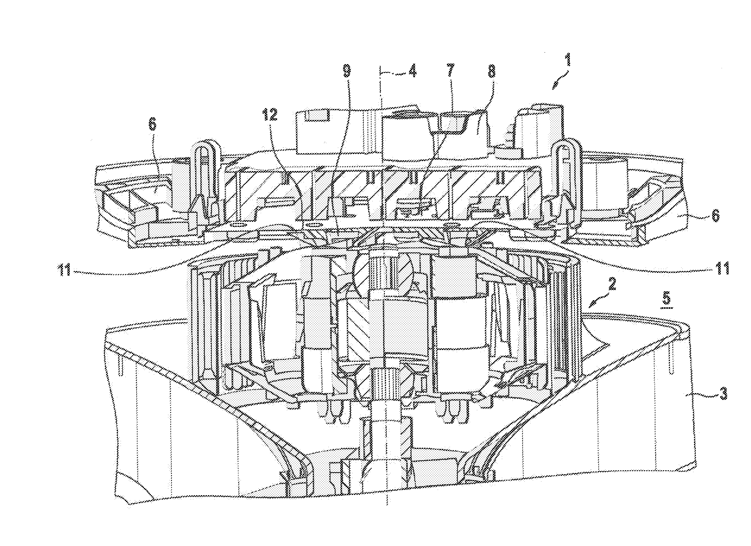
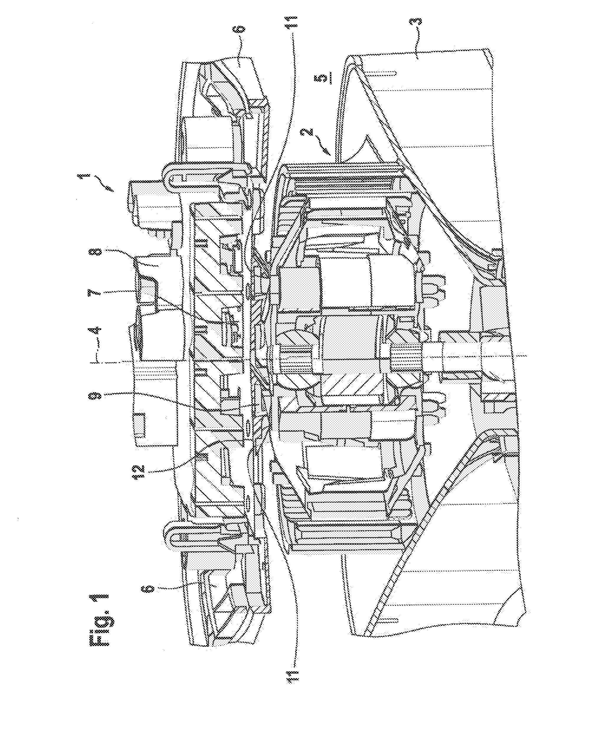
[0021]FIG. 1 shows a region of a fan unit 1, as said device is preferably used in an air conditioning system of a motor vehicle. The fan unit 1 has an electric motor 2 at the disposal thereof, which serves to drive a fan wheel 3. The fan wheel 3 can either be an axial, radial or mixed flow fan wheel. In the exemplary embodiment shown here, a mixed flow fan wheel 3 is used. This represents a combination of an axial and radial fan wheel. An axial section of the fan wheel 3 draws in air in the direction running parallel to a longitudinal axis 4. From the axial section, air enters into a radial section of the fan wheel 3 and flows out of the same substantially in the radial direction and therefore in a direction perpendicular to the longitudinal axis 4. In the depicted embodiment, the electric motor is presented as an external rotor motor, wherein a stator of said electric motor is disposed in the radial direction on the interior side and a rotor on the exterior side. The fan wheel 3 is...


PUM


Abstract

A fan unit (1), in particular for an air conditioning system of a motor vehicle, comprising an electric motor (2) for driving a fan wheel (3), an electronic device (7) which generates waste heat and provides electrical current to the electric motor (2) and a fan housing (6), wherein the fan wheel (3) is disposed together with said electric motor (2) in an air guiding region (5) delimited by the fan housing (6). Provision is thereby made for the electronic device (7) to be fastened to the side of the fan housing (6) which faces away from the air guiding region (5) in a heat transferring manner so that a heat transfer connection is formed between said electronic device (7) and said air guiding region (5).

Description

BACKGROUND OF THE INVENTION[0001]The invention relates to a fan unit, in particular for an air conditioning system of a motor vehicle, comprising an electric motor for driving a fan wheel, an electronic device which generates waste heat and provides electrical current to the electric motor and a fan housing, wherein the fan wheel is disposed together with the electric motor in an air guiding region delimited by the fan housing.[0002]Fan units of the aforementioned kind are known from prior art. They are frequently used in air conditioning systems for motor vehicles. The fan unit comprises the electric motor, the electronic device and the fan housing. The electric motor serves thereby to drive a fan wheel which is operatively connected to a rotor of the electric motor. The electronic device supplies the electric motor with electrical current or respectively operates said motor in open- and / or closed-loop control. In this respect, the electronic device particularly has power electroni...

Claims


Application Information

Patent Timeline
IPC IPC(8): F04D29/58F04D23/00
CPCH02K7/14F04D17/16F04D25/082H02K11/0073F04D29/5813H02K5/225F04D29/5806H02K11/33
Inventor MUELLER, ANDREASSCHIEL, ANDREASADRIAN, LUDGEREISENHARDT, HARALDKILAST, BERNDFRANZ, CHRISTIANLUDWIG, MATTHIAS
Owner ROBERT BOSCH GMBH
Why Eureka
Try Eureka