
Apparatus for head end direct air injection with enhanced mixing capabilities

Inactive Publication Date: 2013-04-11
GENERAL ELECTRIC CO
View PDF7 Cites 92 Cited by
  • Summary
  • Abstract
  • Description
  • Claims
  • Application Information

AI Technical Summary

Benefits of technology

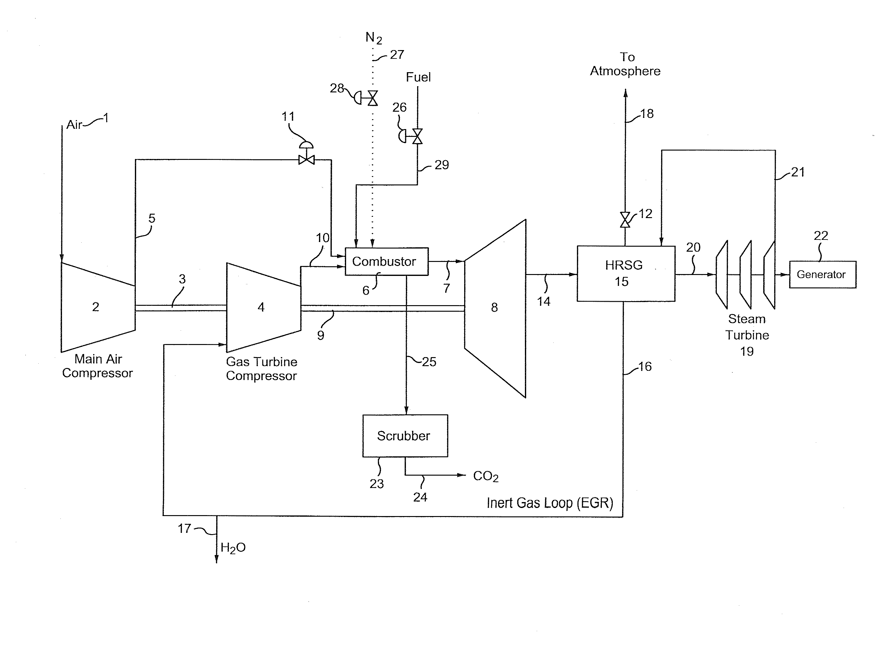
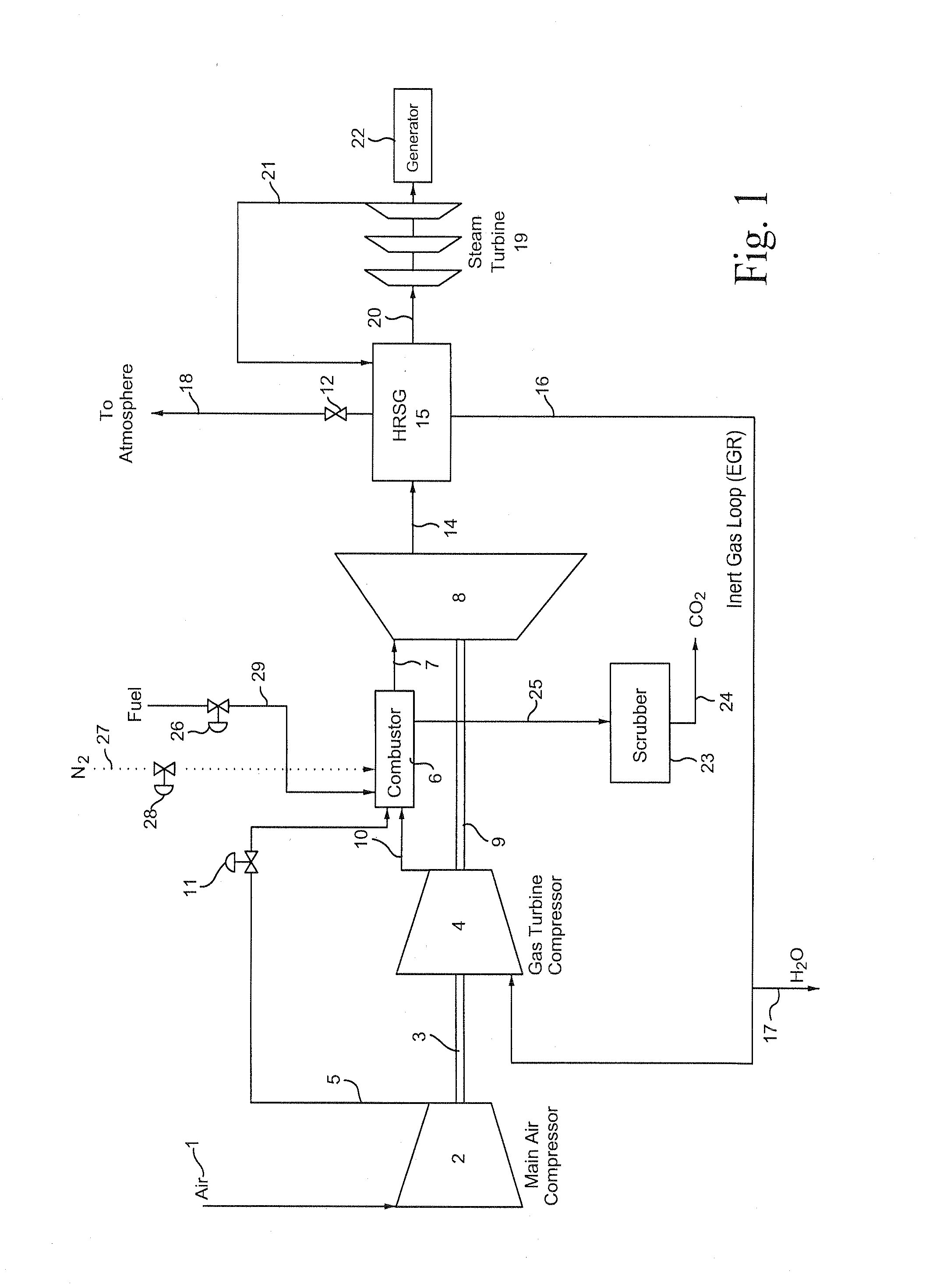
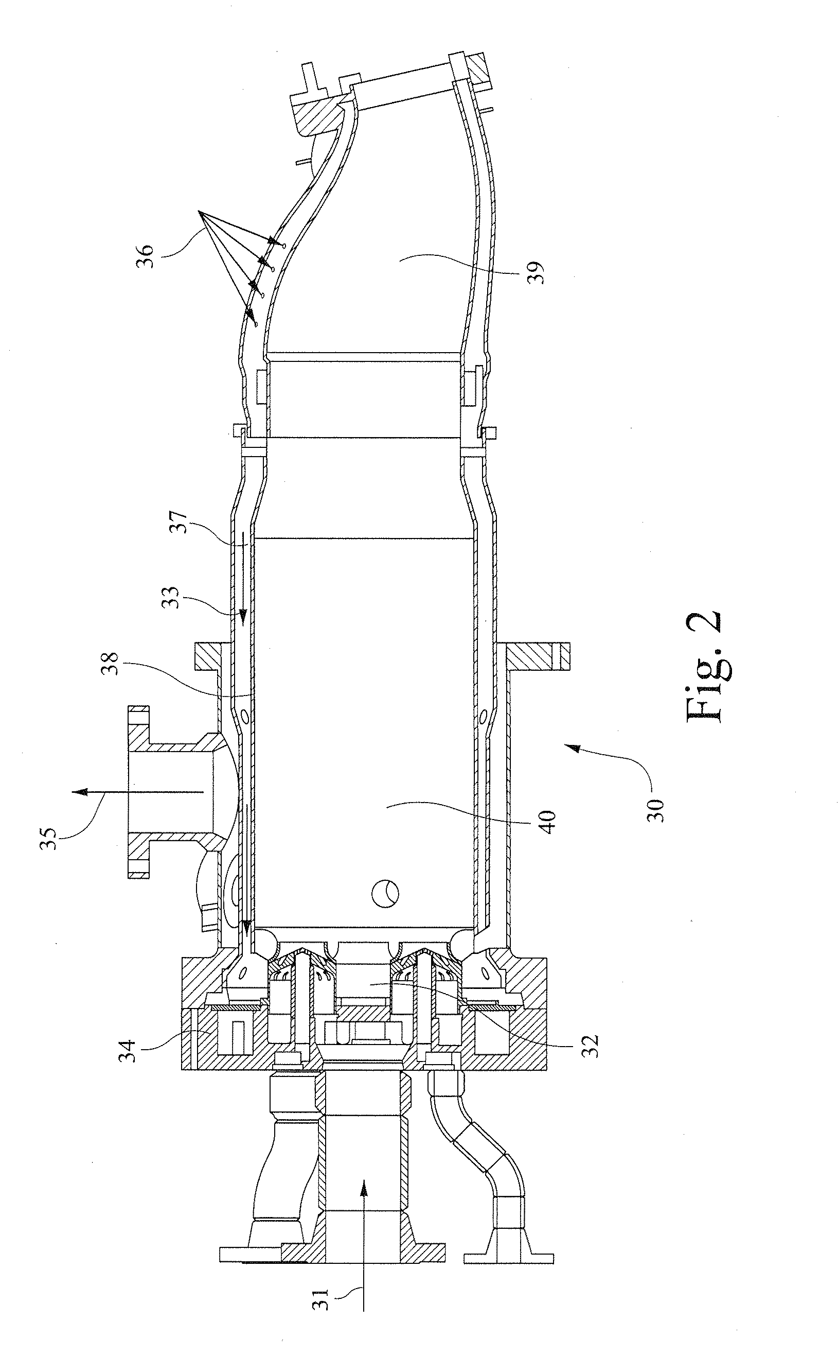
The invention is a new gas turbine engine combustor architecture and method that uses direct air injection and an inert recycle stream as the primary working fluid. This design allows for stochiometric combustion and minimal emissions, and can also adjust NOx and CO emissions through additional diluent injection. The combustor nozzle design also improves mixing of fuel, air, and inert exhaust gas. The invention includes an integrated fuel and air combustion system with a modified fuel supply, compressed external air supply, means for providing the inert exhaust gas recycle stream, and a modified fuel and air nozzle positioned in the head end of the combustor for providing the desired mixing of components prior to ignition.

Problems solved by technology

Most gas turbine engines also tend to operate in a slightly “rich” mode, i.e., with less than the precise stoichiometric amount of oxygen in the feed necessary to burn the entire hydrocarbon fuel mixture, resulting in at least some incomplete combustion, and hence the production of carbon monoxide and other by-products.
Operating at low combustion temperatures in order to lower the NOx emissions can result in incomplete or partially incomplete combustion, which in turn leads to the production of excessive amounts of unburned hydrocarbons and carbon monoxide, as well as lower power output and lower thermal efficiency of the engine.
Higher combustion temperatures, on the other hand, tend to improve thermal efficiency and lower the amount of unburned hydrocarbons and CO, but can still result in a higher amount of NOx if the combustion mixture and operating conditions are not properly monitored and controlled.
First, the fuel to air ratio is subject to finite control since only a limited ability exists to control the exact amount of fuel being fed to each combustor in a multi-combustor design.
Second, individual combustors tend to operate with a slightly different fuel to air ratio, resulting in variations in the emissions on a “can-to-can” basis.
As noted, in the past those design issues have contributed to the need to operate gas turbine engines with a slight amount of excess fuel with all (or virtually all) of the oxygen present in the exhaust eventually being consumed and / or eliminated using catalyst treatment.
However, it has been difficult to control the exact amount of CO produced during the initial combustion, particularly on an individual combustor basis.

Method used


Image

  • Apparatus for head end direct air injection with enhanced mixing capabilities
  • Apparatus for head end direct air injection with enhanced mixing capabilities
  • Apparatus for head end direct air injection with enhanced mixing capabilities

Examples


Embodiment Construction

[0019]The present invention includes means for injecting air directly into the combustor head end along with a significant volume of an inert gas into the combustor at particular specified locations along the exhaust flow path in order to reduce unwanted emissions, particularly CO and oxygen, while improving overall combustor performance. An exemplary system uses a specified amount of exhaust gas recycle (which is substantially inert and at a lower temperature after passing through the turbine) in an amount up to about 50% of the total combustor feed, with the remaining 50% comprising about 5% hydrocarbon fuel and 45% air. The use of an inert gas as part of the working fluid also serves to cool the combustor and reduce the combustor flame temperature while improving the stoichiometry of the gas combustion. That is, it has been found that the inert gas feed helps to establish an equivalence ratio approaching 1.0 for the fuel and oxygen fed to the combustor. Minimizing the final oxyge...


PUM


Abstract

A method for reducing the amount of carbon monoxide and oxygen emissions in a hydrocarbon combustor in a gas turbine engine by feeding hydrocarbon fuel and an oxidizer component into the head end of the combustor while also injecting substantially inert gas into the combustor with the fuel and oxidizer; forming a combustor exhaust stream that mixes with the recycle; cooling the combustor exhaust; detecting the amount of carbon monoxide and oxygen in the exhaust and adjusting the amount of fuel, oxidizer and inert gas feeds based on the detected amounts.

Description

BACKGROUND OF THE INVENTION[0001]The present invention relates to a combustion system for gas turbine engines and, more particularly, to an improved combustor design and method for using direct air injection and a substantially inert gas feed such as an exhaust gas recycle stream (“EGR”) as the primary working fluid. (The terms “inert gas stream” and “substantially inert gas stream” are used interchangeably herein to refer to an EGR type gas stream having small, residual amounts of oxygen). The method and apparatus according to the invention reduce the formation of undesirable gas emissions from the gas turbine engine while increasing the overall efficiency of the combustor.[0002]Gas turbine engines typically include a compressor section, a combustor section and a turbine that rotates to generate electrical power. The compressor discharges higher pressure gas directly into the combustor where hydrocarbon fuel is injected, mixed and burned to produce thermal and kinetic energy. The c...

Claims


Application Information

Patent Timeline
IPC IPC(8): F02C9/00
CPCF23R3/28F23C2202/50F23C2202/30F23C9/00F23R3/10
Inventor SLOBODYANSKIY, ILYA ALEKSANDROVICHKRAEMER, GILBERT OTTOGINESIN, LEONID YUL'EVICHTRETYAKOV, DMITRY VLADLENOVICHSUBBOTA, ANDREY PAVLOVICH
Owner GENERAL ELECTRIC CO
Learn More