Compressor and refrigeration cycle device using same

a compressor and cycle technology, applied in the direction of refrigeration machines, refrigeration components, light and heating apparatuses, etc., can solve the problems of hfc-based refrigerant, and achieve the effect of lowering the deterioration speed of refrigerant and refrigeration

Active Publication Date: 2013-04-25
PANASONIC INTELLECTUAL PROPERTY MANAGEMENT CO LTD
View PDF5 Cites 21 Cited by
  • Summary
  • Abstract
  • Description
  • Claims
  • Application Information

AI Technical Summary

Benefits of technology

[0019]According to the invention, an adsorption film is formed on a surface of a metal member constituting the refrigeration cycle especially on a surface of a compressor sliding member of the compressor, a direct contact between a metal member and refrigeration oil molecule or refrigerant molecule composed of hydrofluoroolefin is suppressed, it is allowed to react with wearing powder which floats in the refrigeration oil or dissolved metal to form inert metal compound to suppress the catalyst function, thereby lowering the deterioration speed of refrigerant and refrigeration oil, and long term reliability of the compressor and the refrigeration cycle device using same can be secured.

Problems solved by technology

However, since this HFC-based refrigerant has extremely high global warming potential (GWP, hereinafter), the HFC-based refrigerant is acknowledged as a problem in recent years in terms of protection of the global environment.

Method used


Image

  • Compressor and refrigeration cycle device using same
  • Compressor and refrigeration cycle device using same
  • Compressor and refrigeration cycle device using same

Examples


first embodiment

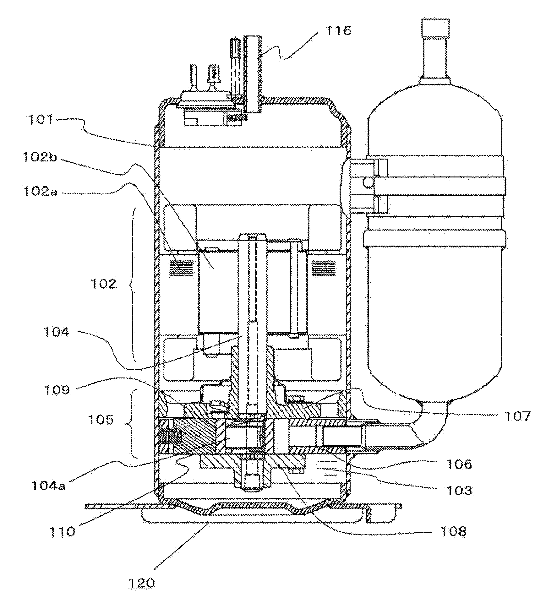
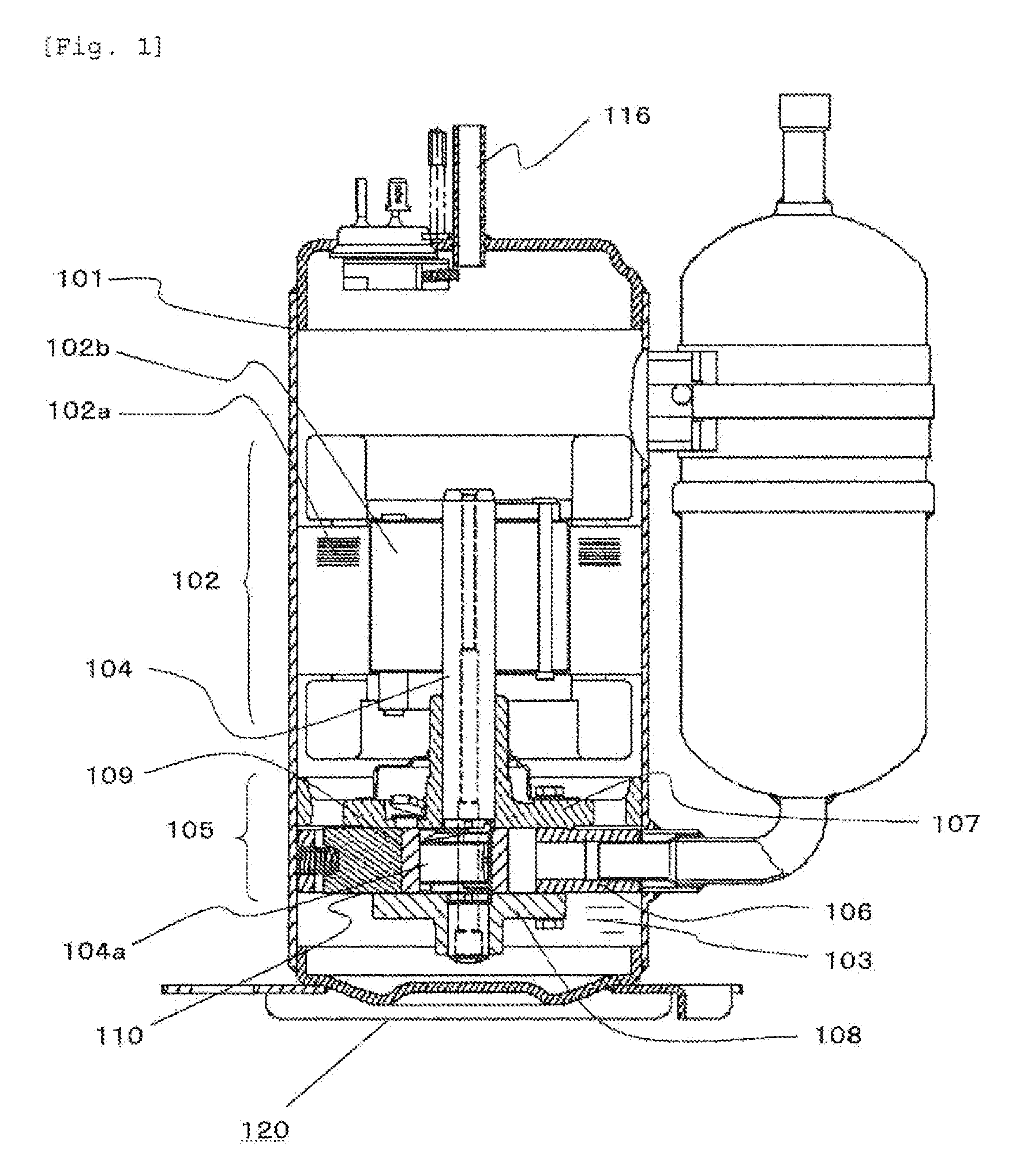
[0038]FIG. 1 is a vertical sectional view of a rotary compressor in a first embodiment of the present invention.

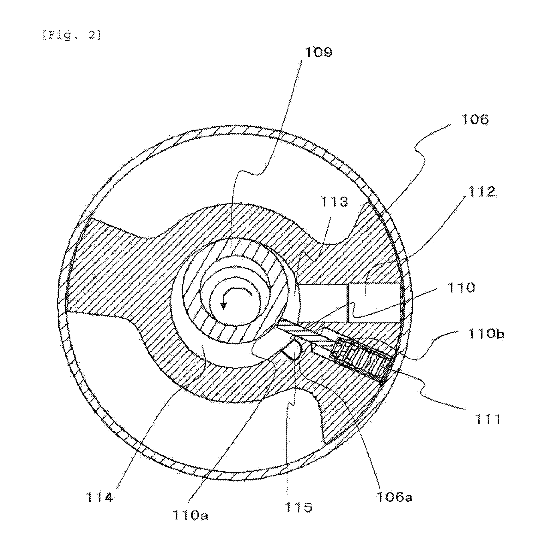
[0039]A stator 102a of a motor 102 is fixed to an upper portion in a container 101, a compressing mechanism 105 including a shaft 104 driven by a rotor 102b is fixed to a lower portion in the container 101. A main bearing 107 is fixed to an upper end of a cylinder 106 of the compressing mechanism 105 through a bolt, and an auxiliary bearing 108 is fixed to a lower end of the cylinder 106 through a bolt. In the cylinder 106, a piston 109 is inserted into an eccentric portion 104a of the shaft 104, and the piston 109 is eccentrically rotated. These members are made of metal material such as iron, copper and aluminum.

[0040]Hydrofluoroolefin (tetrafluoropropene: HF01234yf) having double bond between carbons is charged into the container 101. Refrigeration oil 103 composed of polyol ester having compatibility with the HF01234yf refrigerant is accumulated in a bottom of the cont...

second embodiment

[0074]A second embodiment will be described below based on FIG. 5. The same symbols are allocated to the same configurations as those of the first embodiment, and detailed description thereof will be omitted.

[0075]Here, before an actual machine test using the refrigeration cycle 120 was carried out, to accelerate and evaluate change with the passage of time of deterioration of refrigeration oil, an autoclave test was carried out.

[0076]First, 30 g of refrigeration oil, one copper, one iron and one aluminum each of which became a catalyst and each of which had a diameter of 1.5 mm and a length of 50 mm were placed in the pressure-resistant glass pipe and then, they were stored in a stainless cylinder and the cylinder was evacuated into vacuum. Then, 30 g of a refrigerant was charged thereinto. To facilitate deterioration of the refrigeration oil and the refrigerant, 1000 ppm of moisture and 100 cc of air were also put into the cylinder. The refrigeration oil used in any of combination...


PUM

PropertyMeasurementUnit
lengthaaaaaaaaaa
diameteraaaaaaaaaa
GWPaaaaaaaaaa

Abstract

According to a compressor and a refrigeration cycle device using same of the present invention, a refrigerant and refrigeration oil 103 are sealed in an container 101, the refrigerant is a hydrofluoroolefin having double bond of carbon in its composition or a mixture of hydrofluoroolefin as a base component and hydrofluorocarbon having no double bond, and at least one of benzotriazole, dialkyl dithiophosphoric acid zinc, dialkyl selenium, metal phenate, and organic nitrogen compound is included in the refrigeration oil 103, and it is an object to suppress the decomposition and polymerization of refrigeration oil and a refrigerant, and to secure reliability of the compressor and the refrigeration cycle device.

Description

TECHNICAL FIELD[0001]The present invention relates to enhancement of reliability of a compressor incorporated in a room air conditioner, a refrigerator or an air conditioner using a refrigerant which is mainly composed of hydrofluoroolefin having double bond between carbons of low global warming potential as a working refrigerant, and the invention also relates to enhancement of reliability of a refrigeration cycle device using same.BACKGROUND TECHNIQUE[0002]In conventional compressors and refrigeration cycle devices using same, there is a tendency that HFC (hydrofluorocarbon)-based refrigerant (HFC-based refrigerant, hereinafter) having zero ozone depletion potential is used as a working refrigerant. However, since this HFC-based refrigerant has extremely high global warming potential (GWP, hereinafter), the HFC-based refrigerant is acknowledged as a problem in recent years in terms of protection of the global environment. Hence, a refrigerant which is mainly composed of hydrofluor...

Claims


Application Information

Patent Timeline
Patent Type & Authority Applications(United States)
IPC IPC(8): C09K5/04F25B1/00
CPCC09K2205/24C10M2209/043C10N2210/06F25B2400/121F25B31/026C09K2205/126C10M2209/102C10N2220/302C09K5/045C09K2205/22F25B1/00C10M2219/00C10M2219/083C10M2207/283C10M2215/223C10M2209/062C10M2215/064C10M2209/1033C10M2207/026C10M2219/082C10M2207/028C10N2240/30C10M171/008C10M2223/045C10M2207/044C10M2207/027C10M2227/08C10M2215/065C10M2209/04C10N2210/02C10N2010/12C10N2020/101C10N2040/30C10N2010/04C09K5/04C10M105/18C10M105/38C10M107/24C10M107/34C10M129/10C10M133/12C10M133/38C10M135/00C10M135/20C10M137/10C10M159/22C10M169/04
Inventor ISHIDA, YOSHINORI
Owner PANASONIC INTELLECTUAL PROPERTY MANAGEMENT CO LTD
Why Eureka
Try Eureka