Translucent laminated film and solar cell module using it

Inactive Publication Date: 2013-04-25
ASAHI GLASS CO LTD
View PDF0 Cites 27 Cited by
  • Summary
  • Abstract
  • Description
  • Claims
  • Application Information

AI Technical Summary

Benefits of technology

[0022]The translucent laminated film of the present invention, in an element having a photoelectric conversion layer such as a solar cell module, is capable of making a light in a wavelength region in which the photoelectric conversion efficiency is high, reach the photoelectric conversion layer when being provided on the light receiving side of the photoelectric conversion layer, and can also functi

Problems solved by technology

However, with respect to conventional solar cell modules as disclosed in Patent Documents 1 to 5, the interaction has not necessarily been sufficiently studied.
Accordingly, even with an ef

Method used


Image

  • Translucent laminated film and solar cell module using it
  • Translucent laminated film and solar cell module using it
  • Translucent laminated film and solar cell module using it

Examples


Example

Example 1

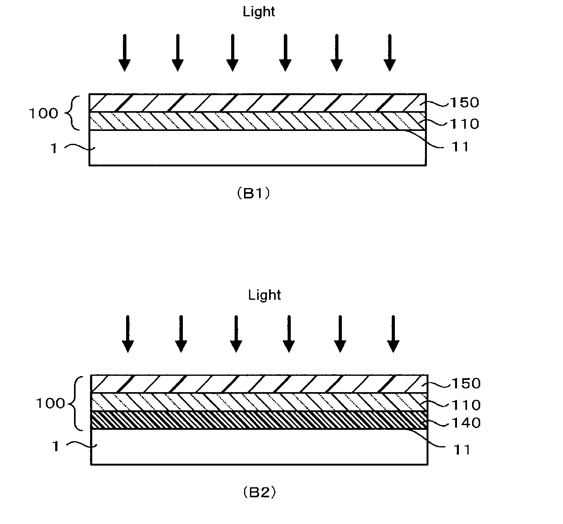
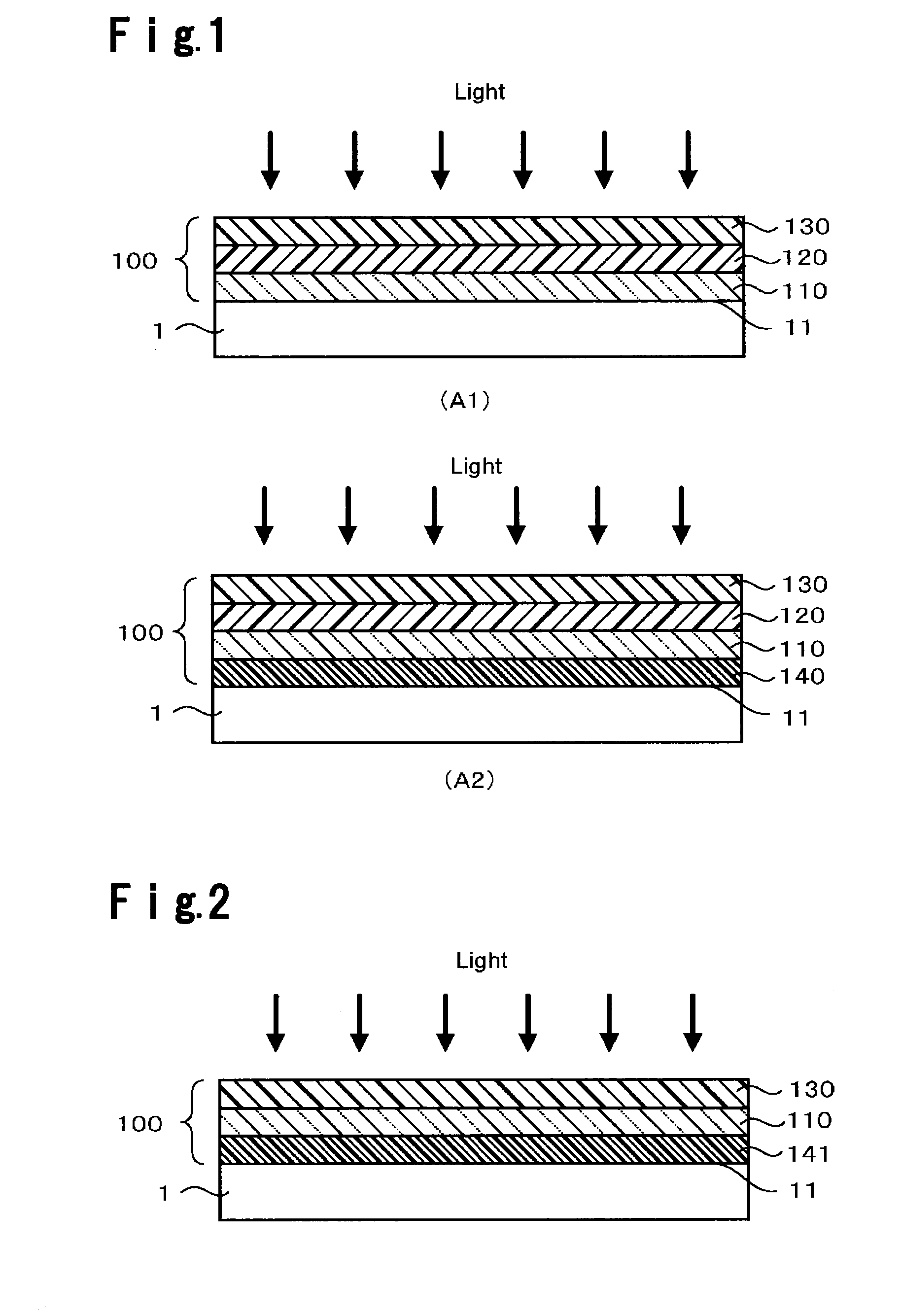
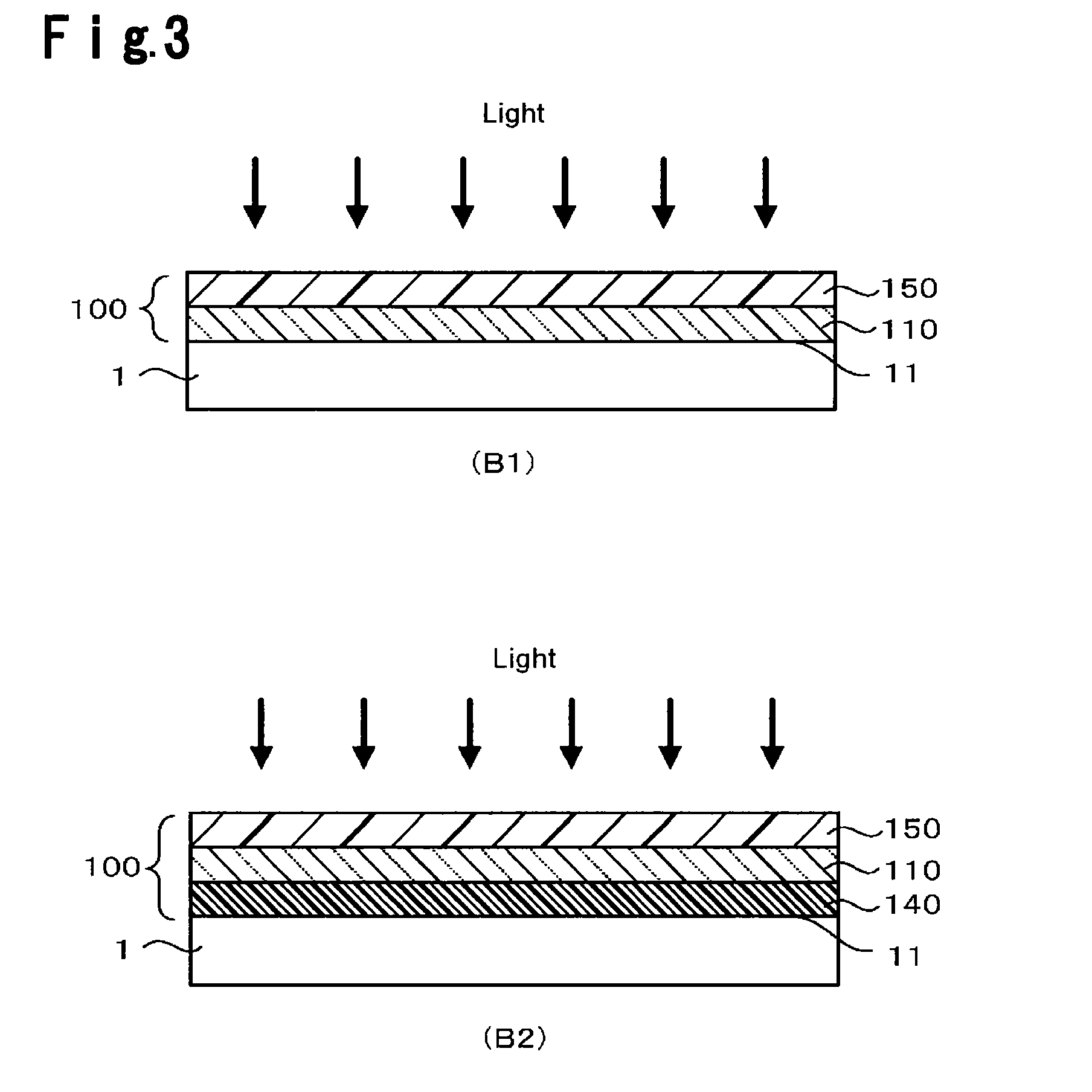
[0218]A step of applying coating fluid A to a non-tin surface of a highly transparent float glass (soda lime glass) substrate (100 mm×100 mm, 4 mm in thickness, average transmittance to a light having a wavelength of from 300 to 400 nm: 75.49%, average reflectance by the above (4): 4.15%, the film refractive index by the above (3): 1.52) washed with cerium oxide, followed by spin coating at 500 rpm for 60 seconds for uniformalization, and firing the coating film at 200° C. for 10 minutes, was repeatedly carried out 10 times to form a substrate front side wavelength conversion film (hereinafter referred to as “first wavelength conversion film”) having a thickness of 1,000 nm, which converts a light in the first wavelength region into a light in the effective wavelength region. Then, coating fluid I was applied on the first wavelength conversion film, followed by spin coating at 500 rpm for 60 seconds for uniformalization, and the coating film was fired at 650° C. for 10 min...

Example

Example 2

[0220]A step of applying coating fluid D to the non-figured surface of a highly transparent figured glass (soda lime glass) substrate (100 mm×100 mm, 3.5 mm in thickness, average transmittance to a light having a wavelength of from 300 to 400 nm: 76.44%, average reflectance by the above (4): 4.16%, film refractive index by the above (3): 1.52) washed with cerium oxide, followed by spin coating at 500 rpm for 60 seconds for uniformalization, and firing the coating film at 200° C. for 10 minutes was repeatedly carried out four times to form a first wavelength conversion film having a thickness of 400 nm. Then, coating fluid I was applied on the first wavelength conversion film, followed by spin coating at 450 rpm for 60 seconds for uniformalization, and the coating film was fired at 650° C. for 10 minutes to form an antireflection film having a thickness of 120 nm.

[0221]Further, coating fluid G was applied on the figured surface of the highly transparent figured glass substr...

Example

Example 3

[0223]A step of applying coating fluid E to the non-figured surface of the same highly transparent figured glass substrate (100 mm×100 mm, 3.5 mm in thickness) as in Example 2 washed with cerium oxide, followed by spin coating at 500 rpm for 60 seconds for uniformalization, and firing the coating film at 200° C. for 10 minutes was repeatedly carried out five times to form a first wavelength conversion film having a thickness of 500 nm. Then, coating fluid I was applied on the first wavelength conversion film, followed by spin coating at 450 rpm for 60 seconds for uniformalization, and the coating film was fired at 650° C. for 10 minutes to form an antireflection film having a thickness of 120 nm. A polycrystalline silicon solar cell was bonded to the figured surface side of the obtained translucent substrate provided with a coating film, whereupon the performance of the solar cell was evaluated. Physical properties of the film and the solar cell performance are shown in Ta...


PUM


Abstract

To provide a translucent substrate which sufficiently improves the power generation efficiency of a solar cell, and a solar cell module.
A translucent laminated film to be provided on the light receiving surface side of a photoelectric conversion layer, which comprises, in order from the light receiving surface side of the photoelectric conversion layer, a translucent substrate which protects the photoelectric conversion layer, a substrate front side wavelength conversion film having a wavelength conversion function to convert a light in a wavelength region in which the photoelectric conversion efficiency is low, which includes a light in a wavelength region in which the transmittance through at least the translucent substrate is low, into a light in a wavelength region in which the photoelectric conversion efficiency is high, and an antireflection film which reduces reflection of the received light.

Description

TECHNICAL FIELD[0001]The present invention relates to a translucent laminated film and a solar cell module using it. More particularly, it relates to a translucent laminated film having at least antireflection function, wavelength conversion function and mechanical strength, and a solar cell module with a good photoelectric conversion efficiency using the laminated film as a protective cover.BACKGROUND ART[0002]For solar cell modules, various attempts have been made in order to increase the photoelectric conversion efficiency.[0003]For example, Patent Document 1 discloses a technique for a solar cell, to provide an antireflection film 1 on a side from which sunlight enters of a transparent protective cover 2, and a layer of a wavelength converter on a side from which the sunlight exits of the transparent protective cover 2 (see FIG. 1). Further, Patent Document 2 discloses a light receiving element comprising a wavelength conversion layer doped with a rare earth metal as dispersed f...

Claims


Application Information

Patent Timeline
IPC IPC(8): H01L31/0203
CPCH01L31/055H01L31/0203H01L31/02168H01L31/0481Y02E10/52C09K11/883C09K11/025C09K11/54C09K11/565C09K11/574C09K11/7794C09K11/02
Inventor KAWAI, YOHEIYONEDA, TAKASHIGE
Owner ASAHI GLASS CO LTD
Why Eureka
Try Eureka