Projection system comprising a solid state light source and a luminsecent material

a technology of solid-state light source and luminsecent material, applied in the direction of optics, lighting and heating apparatus, instruments, etc., can solve the problems of cost and safety issues still being a problem in consumer projection applications, the projection of led based technologies may not be favorable for high brightness requirements, and the projection of led based technologies may look bleak. , to achieve the effect of minimizing thermal influence on each other, good working stability and high thermal stability

Inactive Publication Date: 2013-05-02
KONINKLIJKE PHILIPS ELECTRONICS NV
View PDF7 Cites 17 Cited by
  • Summary
  • Abstract
  • Description
  • Claims
  • Application Information

AI Technical Summary

Benefits of technology

[0071]In a specific embodiment, the projection system may comprise two or more sets of light source units, wherein each light source unit is configured to provide a plurality of emission beams to the corresponding LCD unit (of the 3LCD unit). Especially, the projection system may comprise three sets of light source units, wherein the light source units are configured to provide RGB light, respectively. In this way, a 3LCD system may easily be provided.
[0072]Such architecture may have a high thermal stability, since luminescent material plates, and thermal loads on each of them, are distant from each other and located on effective passive heat sink material (experimental data shows availability to focus a 200 mW laser beam into a spot of 50 μm while having a 100° C. temperature in the spot). Laser diodes used for integration are commonly and widely available. Laser diodes are often mounted in specially designed heat sink material which allows minimizing thermal influence on each other and ensures good working stability. Flexibility in product parameters, e.g. improved color performance, brightness etc., could be achieved by removing one channel of luminescent material plates and placing a partially scattering mini-mirror and using a direct laser source for integration.
[0073]Again, these embodiments may be rather easy to manufacture and may be a cost-effective solution. Further, they may be easy to upgrade (retro application), modify, and scale.

Problems solved by technology

The digital projection industry is exempted from the global ban on Hg containing light sources, since no feasible alternatives exist at this moment.
Said pushing of LED technologies may not be favorable for high brightness requirements, even though these technologies are more efficient.
The perspectives for LED based technologies for projection also look bleak.
Laser technologies are also being considered, but costs and safety issues may still be a problem with respect to consumer projection applications.

Method used


Image

  • Projection system comprising a solid state light source and a luminsecent material
  • Projection system comprising a solid state light source and a luminsecent material
  • Projection system comprising a solid state light source and a luminsecent material

Examples


Embodiment Construction

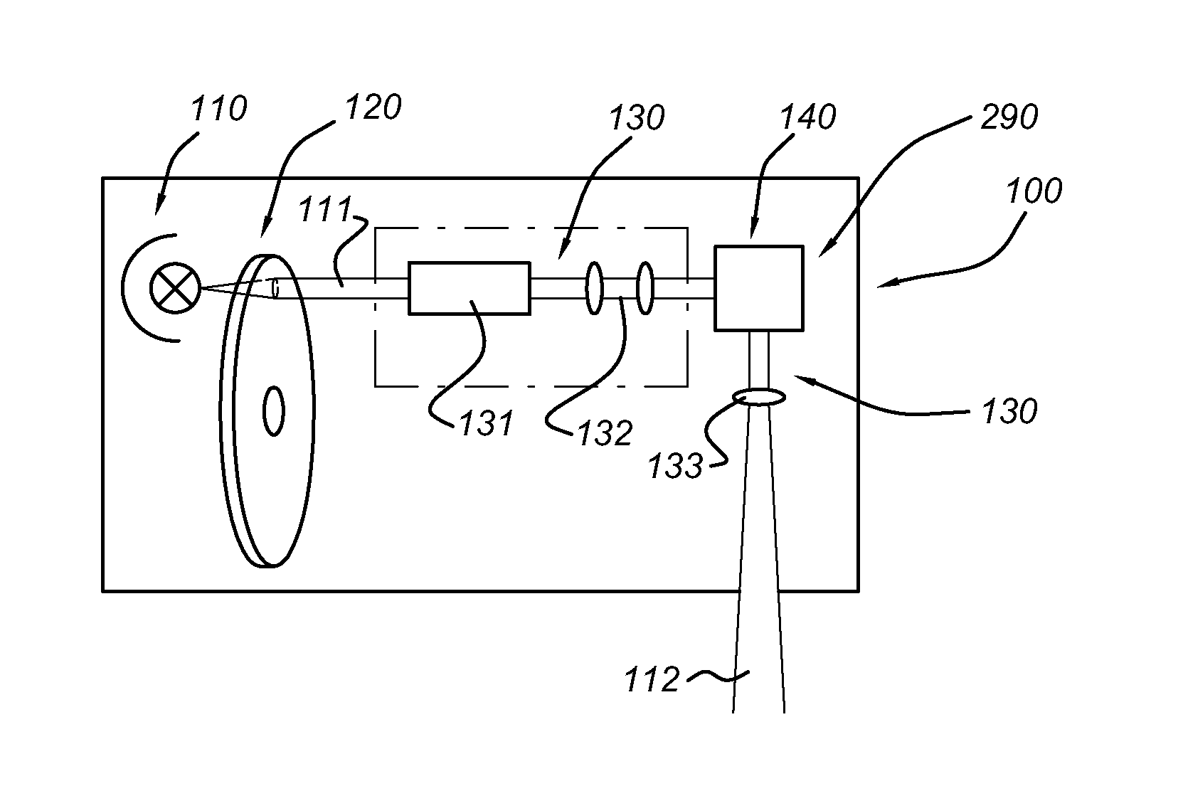
[0087]In general, there are two types of projection systems, DLP-based and 3LCD-based. The projection system is indicated with reference 100.

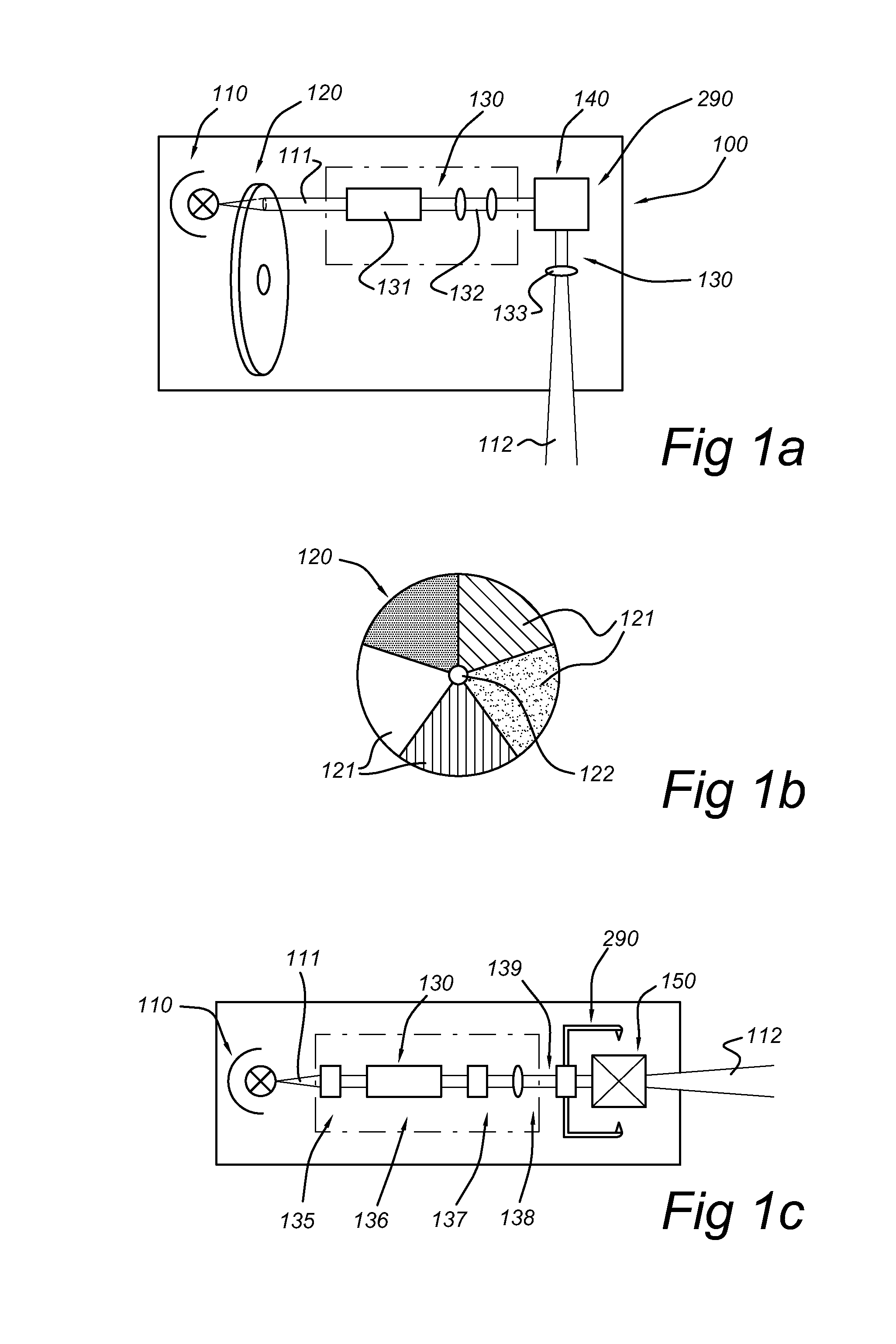
[0088]FIG. 1a schematically depicts a DLP-based projection system 100, which comprises here a light source (UHP-based) 110 generating a beam of light 111, downstream thereof a color wheel 120, downstream thereof optics 130, which in general comprises a homogenizer 131, such as a light tunnel, integrating rod or fly eye, and one or more lenses or minors 132. Downstream thereof, a DLP unit 140, as an example of an image panel 290, is arranged. Downstream thereof, again some optics may be found, such as one or more lenses 133. The projection system 100 provides projection beam 112.

[0089]FIG. 1b schematically depicts a version of a color wheel 120, with color filters 121. The color wheel may comprise one or more of those filters, but may also comprise a colorless transparent part. Here, the wheel has a disk-like shape.

[0090]FIG. 1c schematically de...


PUM


Abstract

The invention provides a projection system (100) comprising a projection light source (110) and a color wheel (120), wherein the projection light source (110) comprises a solid state light source (115), configured to generate a solid state light source beam (111) having a solid state light source beam cross-section. Upstream of the color wheel (120) beam shaping optics (161) are arranged, configured to shape the solid state light source beam cross-section into a rectangular cross-section. The color wheel (120) comprises regions (125) of different luminescent material (170), excitable by the solid state light source beam (111) and configured to generate, upon excitation by the solid state light source beam (111), visible light (116) for projection on an image panel (290). The regions (125) are arranged at different distances from an axis of rotation (122) of the color wheel (120).

Description

FIELD OF THE INVENTION[0001]The invention relates to a digital projection system, such as a DLP-based projection system or a 3LCD-based projection system.BACKGROUND OF THE INVENTION[0002]Projection systems have been known for a long time, and there is still a desire to improve such projection systems.[0003]US2005174544 for instance describes a light source for an image projection system comprising one or more LEDs packaged for high temperature operation. Advantageously, the LED dies are disposed on a package comprising a ceramic-coated metal base including one or more underlying thermal connection pads, and underlying electrical connection pads, each LED die being thermally coupled through the metal base to a thermal connection pad and electrically coupled to electrical connection pads. The LED can be mounted directly on the metal of the base or on a thin coating of electrical insulator on the metal. Arrays of LED dies thus packaged are advantageously fabricated by means of the low-...

Claims


Application Information

Patent Timeline
Patent Type & Authority Applications(United States)
IPC IPC(8): G03B21/14F21V9/08
CPCH04N9/315F21V9/08G03B21/202G03B21/204G03B21/14G03B21/2033G03B21/208
Inventor AKSENOV, YURI
Owner KONINKLIJKE PHILIPS ELECTRONICS NV
Why Eureka
Try Eureka