High fidelity patterning employing a fluorohydrocarbon-containing polymer

a fluorohydrocarbon and polymer technology, applied in the field of high-fidelity patterning employing a high density plasma, can solve the problems of difficult identification of novel patterning materials capable soft material mechanical failure, and substantial problems, and achieve the effect of high-fidelity pattern transfer

Inactive Publication Date: 2013-05-02
GLOBALFOUNDRIES INC +1
View PDF4 Cites 20 Cited by
  • Summary
  • Abstract
  • Description
  • Claims
  • Application Information

AI Technical Summary

Benefits of technology

[0005]A stack of a hard mask layer and a soft mask layer is deposited on a substrate. A photoresist is applied over the soft mask layer, and is lithographically patterned to form at least one opening therein. The pattern of the at least one opening is transferred into the soft mask layer by an anisotropic etch, which forms a carbon-rich polymer that includes more carbon than fluorine. The carbon-rich polymer can be formed by employing a fluorohydrocarbon-containing plasma generated with fluorohydrocarbon molecules including more hydrogen than fluorine. The carbon-rich polymer coats the sidewalls of the soft mask layer, and prevents widening of the pattern transferred into the soft mask. The pattern in the soft mask layer is transferred into the hard mask layer. Sidewalls of the hard mask layer are coated with the carbon-rich polymer to prevent widening of the pattern transferred into the hard mask. The carbon-rich polymer effects high fidelity pattern transfer by minimizing lateral widening of openings within the soft mask layer and within the hard mask layer.

Problems solved by technology

The deformation of the pattern is known to originate from substantial modification of the soft material by the plasma that eventually leads to mechanical failure of the soft material.
In particular, interaction of a plasma polymer with a soft patterning material can cause substantial problems.
Suitable novel patterning materials capable of a high fidelity pattern transfer are difficult to identify.
Hardening processes require treatment at elevated temperatures, which can adversely impact device performance due to the undesirable effect of additional thermal cycling on device performance.

Method used


Image

  • High fidelity patterning employing a fluorohydrocarbon-containing polymer
  • High fidelity patterning employing a fluorohydrocarbon-containing polymer
  • High fidelity patterning employing a fluorohydrocarbon-containing polymer

Examples


first embodiment

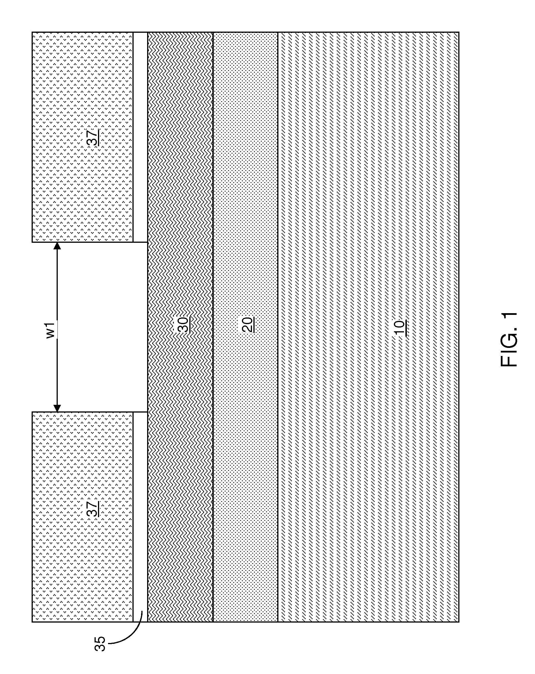
[0022]Referring to FIG. 1, a first exemplary structure according to the present disclosure includes a substrate 10, a hard mask layer 20, a soft mask layer 30, and a photoresist 37.

[0023]The substrate 10 can include a semiconductor material, an insulator material, a conductive material, or a combination thereof. The semiconductor material can be an elemental semiconductor material such as silicon, germanium, carbon, or an alloy thereof, a III-V compound semiconductor material, a II-VI compound semiconductor material, or any combination or stack thereof. The semiconductor material can be doped with electrical dopants such as B, Ga, In, P, As, and Sb. Multiple semiconductor materials can be present in the substrate. The insulator material can be doped or undoped silicon oxide, doped derivatives of silicon oxide, silicon nitride, silicon oxynitride, a dielectric metal oxide having a dielectric constant greater than 3.9, or a combination or stack thereof. Multiple insulator materials ca...

second embodiment

[0068]Referring to FIG. 7, a second exemplary structure according to the present disclosure is derived from the first exemplary structure of FIG. 1 by substituting a stack of multiple hard mask layers for the hard mask layer 20 in the first exemplary structure. For example, a stack, from bottom to top, of a lower hard mask layer 20′ and an upper hard mask layer 20″. Each of the lower hard mask layer 20′ and the upper hard mask layer 20 can have any of the material that can be employed for the hard mask layer 20 in the first exemplary structure. The thickness of each of the lower hard mask layer 20′ and the upper hard mask layer 20″ can be the same as the thickness of the hard mask layer 20. The lower hard mask layer 20′ and the upper hard mask layer 20″ have different compositions. Each of the lower hard mask layer 20′ and the upper hard mask layer 20″ can be formed, for example, by chemical vapor deposition (CVD).

[0069]Referring to FIG. 8, the processing steps of FIGS. 2-4 accordin...


PUM

PropertyMeasurementUnit
dielectric constantaaaaaaaaaa
thicknessesaaaaaaaaaa

Abstract

A stack of a hard mask layer, a soft mask layer, and a photoresist is formed on a substrate. The photoresist is patterned to include at least one opening. The pattern is transferred into the soft mask layer by an anisotropic etch, which forms a carbon-rich polymer that includes more carbon than fluorine. The carbon-rich polymer can be formed by employing a fluorohydrocarbon-containing plasma generated with fluorohydrocarbon molecules including more hydrogen than fluorine. The carbon-rich polymer coats the sidewalls of the soft mask layer, and prevents widening of the pattern transferred into the soft mask. The photoresist is subsequently removed, and the pattern in the soft mask layer is transferred into the hard mask layer. Sidewalls of the hard mask layer are coated with the carbon-rich polymer to prevent widening of the pattern transferred into the hard mask.

Description

BACKGROUND[0001]The present disclosure relates to semiconductor processing methods, and particularly to methods for high fidelity patterning employing a high density plasma, and structures for effecting the same.[0002]Pattern transfer at small dimensions and small pitch solutions requires high precision. A typical phenomenon for pattern transfer at small dimension is the deformation of the patterning materials as a result of plasma processing. The deformation typically occurs when a mask in a soft (carbon-based) material is transferred into a harder material (such as a semiconductor material, silicon oxide, silicon nitride, silicon oxynitride, and metallic materials).[0003]The deformation of the pattern is known to originate from substantial modification of the soft material by the plasma that eventually leads to mechanical failure of the soft material. In particular, interaction of a plasma polymer with a soft patterning material can cause substantial problems.[0004]Proposed soluti...

Claims


Application Information

Patent Timeline
Patent Type & Authority Applications(United States)
IPC IPC(8): B32B3/00C23F1/02
CPCG03F7/091G03F7/094G03F7/40H01L21/0332H01L21/31116H01L21/31122H01L21/31138H01L21/31144Y10T428/24479
Inventor BRINK, MARKUSENGELMANN, SEBASTIAN U.FULLER, NICHOLAS C. M.GUILLORN, MICHAEL A.MIYAZOE, HIROYUKINAKAMURA, MASAHIRO
Owner GLOBALFOUNDRIES INC
Why Eureka
Try Eureka