Antenna system optimized for siso and MIMO operation

a technology of siso and mimo, applied in the field of wireless communication, can solve the problems of interference at the receiving antenna, degradation of device performance, and blockage of the line of sight between the transmitter and the receiver involved in the communication,

Active Publication Date: 2013-05-02
KYOCERA AVX COMPONENTS (SAN DIEGO) INC
View PDF6 Cites 34 Cited by
  • Summary
  • Abstract
  • Description
  • Claims
  • Application Information

AI Technical Summary

Problems solved by technology

In many instances, the line of sight between a transmitter and a receiver involved in the communication becomes blocked or shadowed with obstacles such as walls and other objects.
Each signal bounce may introduce phase shifts, time delays, attenuations and distortions, which ultimately interfere at the receiving antenna.
Destructive interference in the wireless link is problematic and results in degradation of device performance.
However, in a MIMO system, each radio link between one of the Rx antennas and one of the TX antennas may still face destructive interferences due to phase shifts, time delays, attenuations, distortions and various other electromagnetic effects as explained earlier.
In such a configuration with multiple antennas, size constraints may become significant, and coupling among the antennas as well as between the antennas and nearby electronics of a communication device may significantly deteriorate transmission and reception qualities.
Additionally, efficiency may deteriorate in many instances where multiple paths are energized and power consumption increases.
Implementing two, three or more diversity antennas may provide system flexibility, but the volume and area requirements become increasingly severe as additional antennas, associated components and transmission lines are needed.
As such, mixing diversity and MIMO techniques has gained limited popularity thus far.
For handheld mobile devices the problem is exacerbated by antenna detuning caused by the multiple use cases of a device: hand loading of the cell phone, cell phone placed to user's head, cell phone placed on metal surface, etc.
For cell phone applications, the multipath environment is constantly changing, which impacts throughput performance of the communication link.
For a majority of cases, such as low signal strength regions, high multipath environments and issues involving deep signal fading, a single antenna will not provide the data rate required for Category 1 operation.
The problems associated with implementing four antennas in a mobile device for use in a cellular network are numerous: making volume internal to a mobile device available for four antennas, providing a four port transceiver configured for MIMO operation, the power consumption of a four port solution compared to a two port solution, and the difficulty of integrating four antennas into a mobile device while maintaining high isolation and low correlation between the antennas.

Method used


Image

  • Antenna system optimized for siso and MIMO operation
  • Antenna system optimized for siso and MIMO operation
  • Antenna system optimized for siso and MIMO operation

Examples


Embodiment Construction

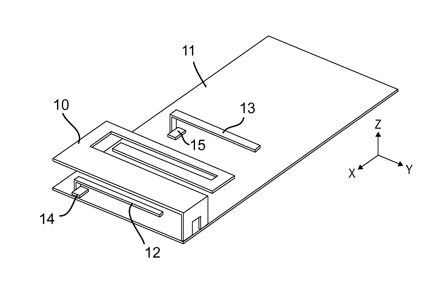
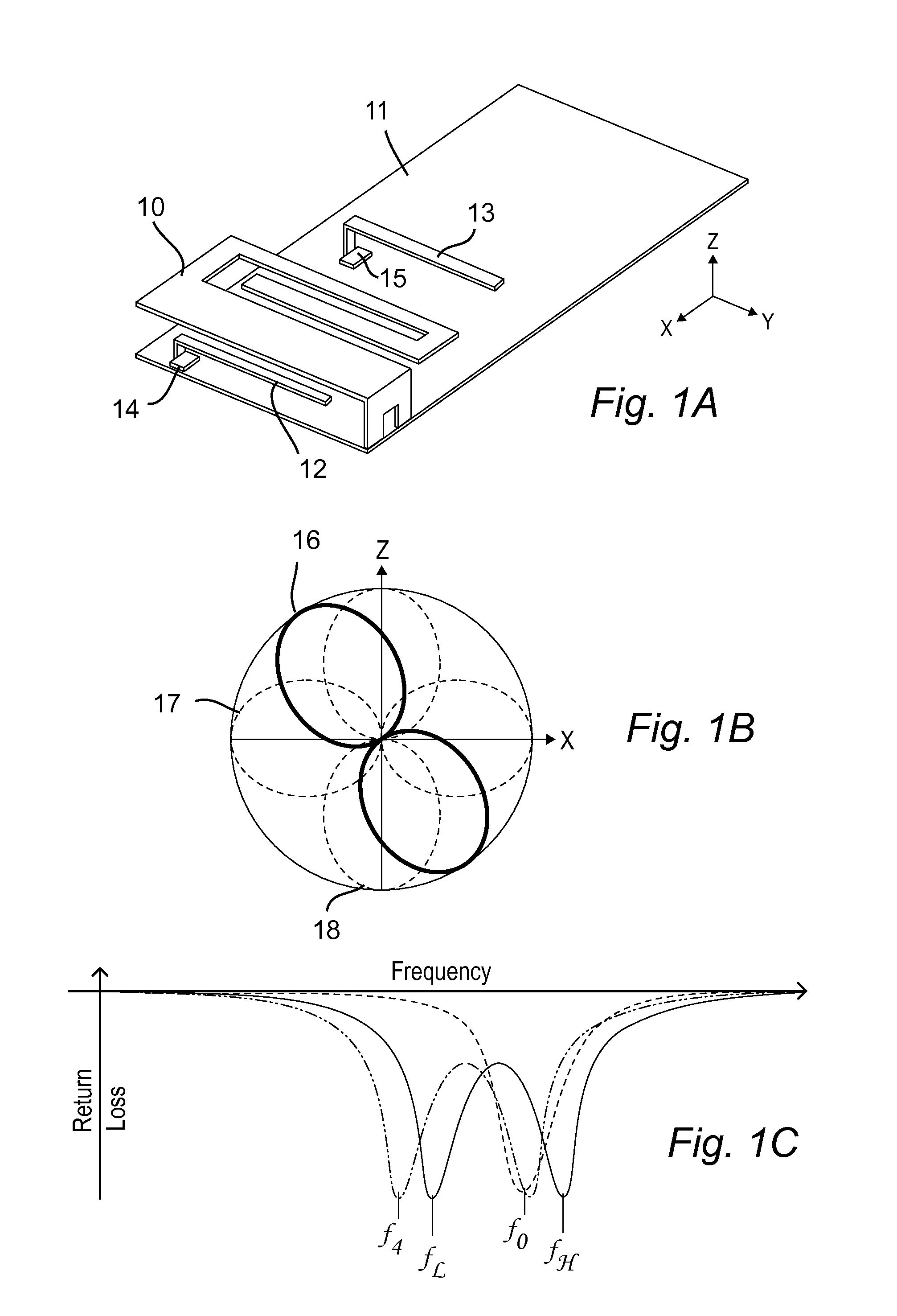
[0031]Commonly owned U.S. Pat. Nos. 7,830,320 and 7,911,402 describe antennas and methods for active band switching and a beam steering technique, respectively, wherein a single antenna is capable of generating multiple radiating modes; the contents of which are incorporated by reference. These antennas being capable of generating multiple antenna radiation modes are herein referred to as “modal antennas”. These band switching (frequency shifting) and beam steering techniques are effectuated with the use of offset parasitic elements strategically disposed adjacent to the antenna radiator and adapted to alter the current distribution on the driven antenna as the reactive load on the parasitic is varied.

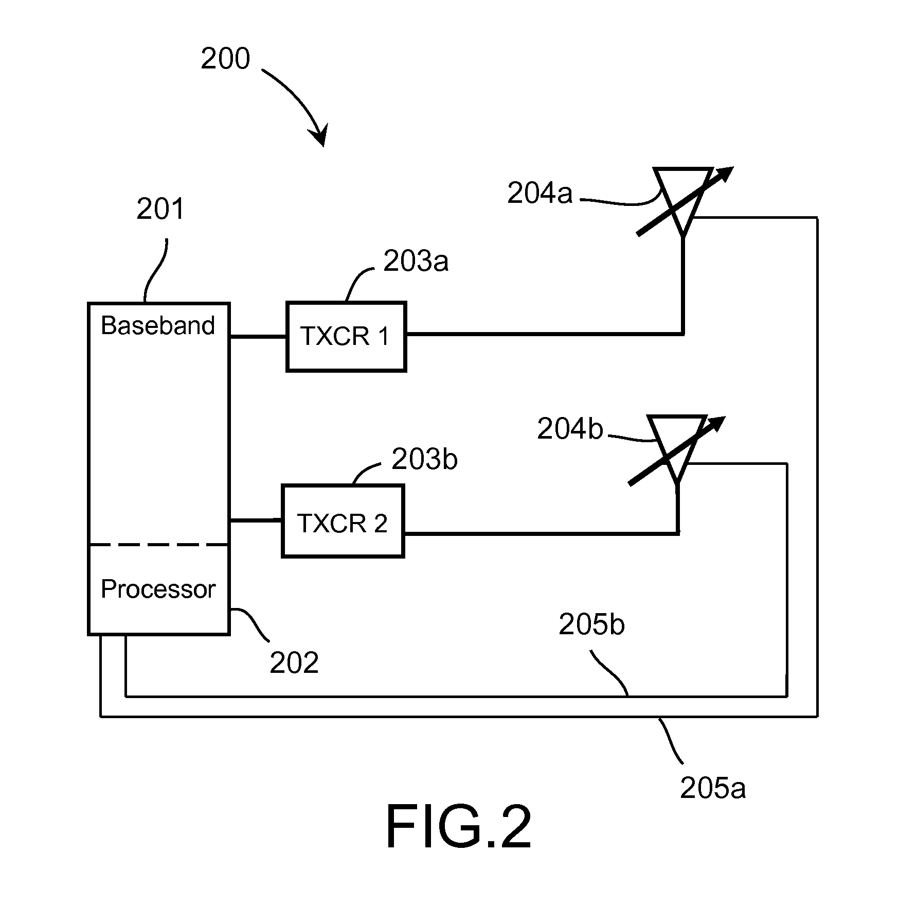
[0032]One application identified for this technique includes a novel receive diversity technique described in U.S. patent application Ser. No. 13 / 227,361, filed Sep. 07, 2011, titled “MODAL ANTENNA WITH CORRELATION MANAGEMENT FOR DIVERSITY APPLICATIONS”, wherein a single modal antenna ...


PUM


Abstract

An active antenna system and algorithm is described that provides for improved performance from LTE communication systems operating in Category 1 mode, where one antenna is used. For the LTE SISO case (category 1), a modal antenna capable of generating multiple radiation patterns will provide improved throughput due to improved resistance to fading. Modal (Null Steering) antenna technology is implemented in a multi-antenna system to provide for single and multiple antenna operation wherein one or more antennas have two or more radiation modes. An algorithm has been developed that determines when to switch from SISO to MIMO operation.

Description

CROSS-REFERENCE TO RELATED APPLICATIONS[0001]This application is a continuation-in-part of U.S. patent application Ser. No. 13 / 029,564, filed Feb. 17, 2011, titled “ANTENNA AND METHOD FOR STEERING ANTENNA BEAM DIRECTION”, which is a CON of U.S. patent application Ser. No. 12 / 043,090 , filed Mar. 05, 2008, titled “ANTENNA AND METHOD FOR STEERING ANTENNA BEAM DIRECTION”, now U.S. Pat. No. 7,911,402, issued Mar. 22, 2011;[0002]a continuation-in-part of U.S. patent application Ser. No. 12 / 894,052, filed Sep. 29, 2010, titled “ANTENNA WITH ACTIVE ELEMENTS”, which is a CON of U.S. patent application Ser. No. 11 / 841,207 , filed Aug. 20, 2007, titled “ANTENNA WITH ACTIVE ELEMENTS”, now U.S. Pat. No. 7,830,320, issued Nov. 9, 2010;[0003]a continuation-in-part of U.S. patent application Ser. No. 13 / 227,361, filed Sep. 07, 2011, titled “MODAL ANTENNA WITH CORRELATION MANAGEMENT FOR DIVERSITY APPLICATIONS”; and[0004]claims benefit of priority to U.S. Provisional Ser. No. 61 / 535,360, filed Sep. ...

Claims


Application Information

Patent Timeline
Patent Type & Authority Applications(United States)
IPC IPC(8): H04B7/04
CPCH04B7/0413H01Q9/0421H01Q3/00H01Q1/243
Inventor DESCLOS, LAURENTROWSON, SEBASTIANSHAMBLIN, JEFFREY
Owner KYOCERA AVX COMPONENTS (SAN DIEGO) INC
Why Eureka
Try Eureka