Full spectrum solid state white light source, method for manufacturing and applications

Active Publication Date: 2013-05-09
RENESSELAER POLYTECHNIC INST
View PDF10 Cites 5 Cited by
  • Summary
  • Abstract
  • Description
  • Claims
  • Application Information

AI Technical Summary

Benefits of technology

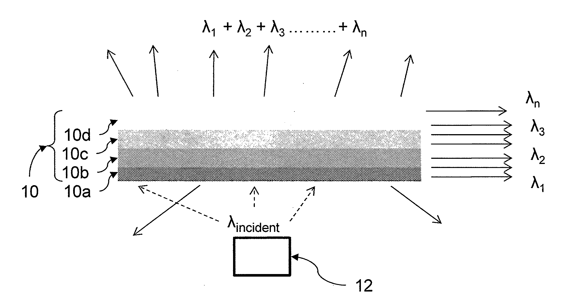
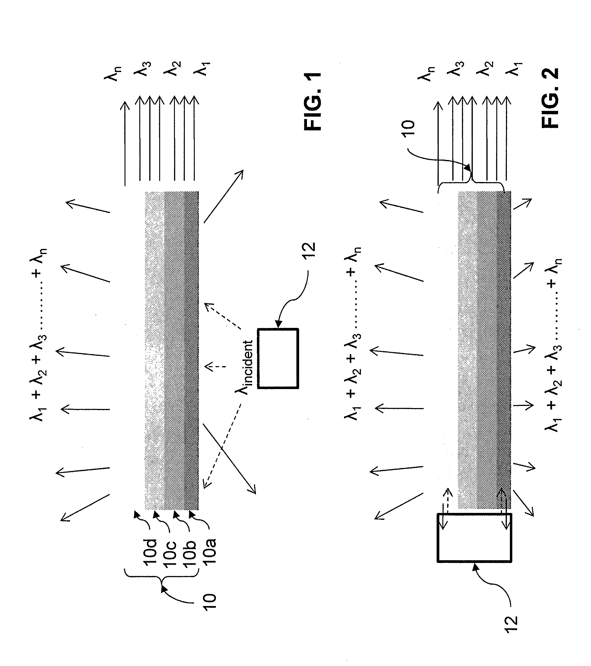
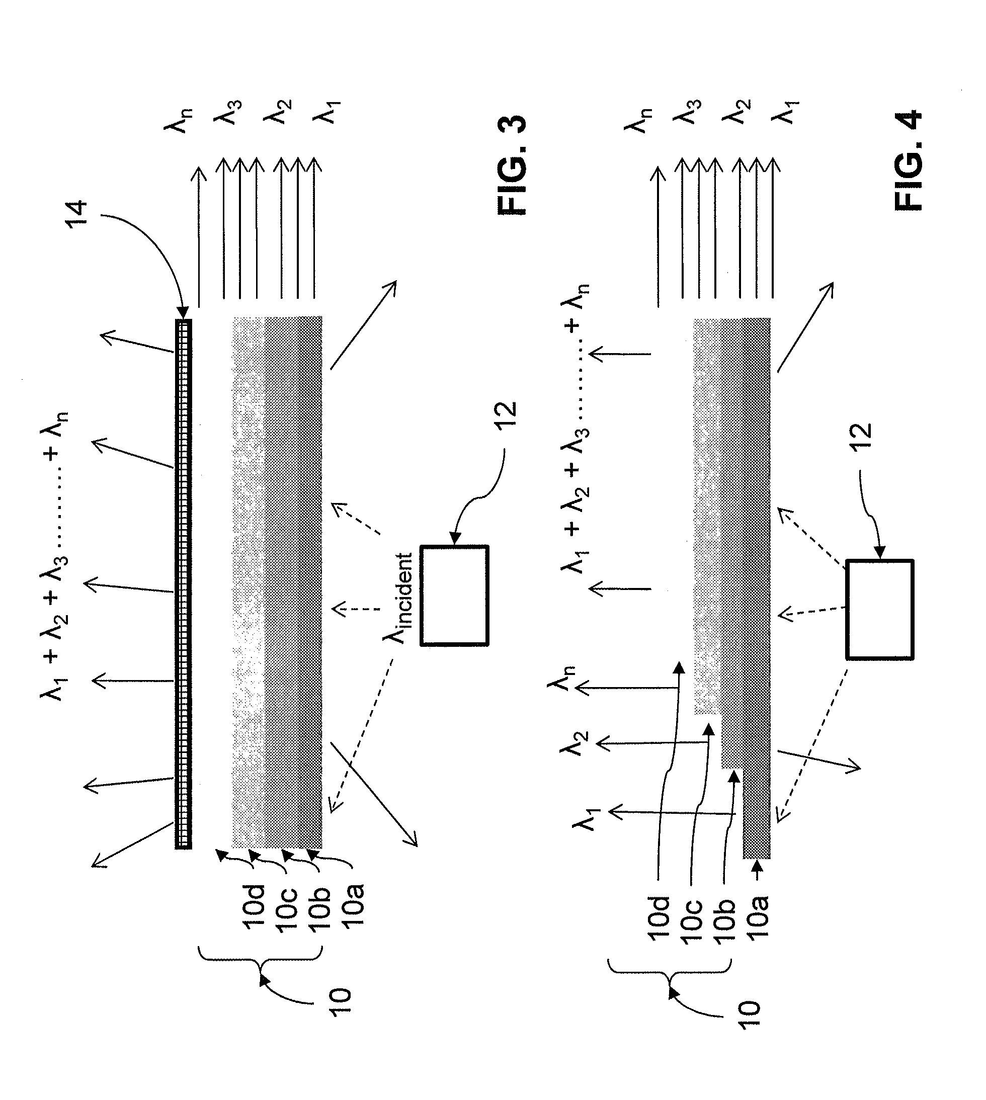
[0015]The down-conversion material, in the embodiments of the present invention, may be disposed remotely, i.e., away from the light source(s), adjacent to the light source, embedded within the light source, or a number of other configurations. One or more down-converting materials are used to absorb radiation in one spectral region and emit radiation in another spectral region. Multiple down-converting materials are capable of converting the wavelength emitted from the light source to the same or different spectral regions. The down-conversion materials may be mixed together or employed as individual layers. By capturing both the forward transferred portion and the back transferred portion of the down-converted light, system efficiency may be improved. Additional components may be employed to enhance the directional light output, aesthetics, or light quality of the light systems of the present invention including, for example, reflectors, diffraction gratings, and light guides. Similarly, the position of the

Problems solved by technology

Due to their long operation (burn) time and low power consumption, solid-state light emitting devices frequently provide a functional cost benefit, even when their initial cost is greater than that of conventional lamps.
These traditional methods, however, are generally ineffective for the production of LEDS capable of emitting a multitude of individual wavelengths because it is difficult to control the conversion properties of the blended phosphors.
This prevents the phosphor from being optically transparent or translucent and r

Method used


Image

  • Full spectrum solid state white light source, method for manufacturing and applications
  • Full spectrum solid state white light source, method for manufacturing and applications
  • Full spectrum solid state white light source, method for manufacturing and applications

Examples


example

[0071]The invention will now be described by use of a non-limiting example. It will be understood that any number of the materials, substrates, systems, and the like described above may be used or configured in a number of different ways and be within the teachings of the present invention.

[0072]FIG. 9 shows a plot of the emission spectrum from a typical blue LED excitation source. As can be seen from the figure, the blue LED produces a limited wavelength emission range around 450 nm. FIG. 10, comparatively, shows a plot of the emission spectrum from a typical blue LED excitation source that has been passed through a graded crystalline phosphor substrate according to at least one embodiment of the present invention. The crystalline phosphor substrate tested was a graded composition of an alkaline earth metal thiogallate which typically has the formula MxMyA2aA2bS4 Eu2+; where M is one or more elements selected from the group consisting of Be, Mg, Ca, Sr, Ba, and Zn; and A is one or ...


PUM


Abstract

A method of manufacturing a down-conversion substrate for use in a light system includes forming a first crystallography layer including one or more phosphor materials and, optionally, applying at least one activator to the crystallography layer, heating the crystallography layer at high temperature to promote crystal growth in the crystallography layer, and drawing out the crystallography layer and allowing the crystallography layer to cool to form the down-conversion substrate. A light system includes an excitation source for emitting short wavelength primary emissions; and a down-conversion substrate disposed in the path of at least some of the primary emissions from the excitation source to convert at least a portion of the primary emissions into longer-wavelength secondary emissions, wherein the substrate includes one or more crystallography layers, wherein each crystallography layer includes one or more phosphor materials, and optionally at least one activator. Down-converted secondary light may be produced by the system.

Description

CROSS-REFERENCE TO RELATED APPLICATIONS[0001]This application claims the benefit of priority to U.S. Provisional Application Ser. No. 61 / 399,890, filed Jul. 19, 2010, the disclosure of which is incorporated in its entirety by reference herein for all purposes.FIELD OF THE INVENTION[0002]The present invention relates generally to down-conversion lighting systems. Specifically, the present invention relates to methods of manufacturing down-conversion substrates, down-conversion light systems incorporating the substrates, and methods of producing down-converted secondary light emissions.BACKGROUND OF THE INVENTION[0003]Solid-state light (SSL) emitting devices, including solid-state light fixtures having light emitting diodes (LEDs) are extremely useful, because they potentially offer long term durability benefits over conventional light fixtures, such as those that utilize incandescent and fluorescent lamps. Due to their long operation (burn) time and low power consumption, solid-state...

Claims


Application Information

Patent Timeline
IPC IPC(8): H01L33/58H01L33/00H01L33/44F21V9/40
CPCC09K11/7731H01L33/502H01L33/504H01L2933/0041B82Y30/00Y02B20/181H01L33/44H01L33/58Y10S977/774Y10S977/949H01L33/005Y02B20/00
Inventor DUTTA, PARTHA S.
Owner RENESSELAER POLYTECHNIC INST
Why Eureka
Try Eureka