
Transparent electrode for thin film solar cell, substrate having transparent electrode for thin film solar cell and thin film solar cell using same, and production method for transparent electrode for thin film solar cell

Active Publication Date: 2013-05-16
KANEKA CORP
View PDF4 Cites 7 Cited by
  • Summary
  • Abstract
  • Description
  • Claims
  • Application Information

AI Technical Summary

Benefits of technology

The present invention provides a transparent electrode for thin film solar cells with surface irregularities made of zinc oxide film. This electrode has high light confinement and low carrier concentration, and is resistant to humidity-induced degradation. The use of this electrode improves the performance of thin film solar cells.

Problems solved by technology

However, since the SnO2 film should be deposited by a high-temperature process at about 550 to 650° C., inexpensive substrates such as a plastic film and glass after solidification cannot be used, and therefore production costs are increased.
However, when the carrier concentration in the film exceeds a certain level, the resistance is no longer lowered, and the light transmittance of the ZnO film decreases due to light absorption by carriers, so that the current density of a solar cell is reduced.
If the ZnO thin film as a transparent electrode of a thin film solar cell has increased resistance as described above, the series resistance of the solar cell increases, so that characteristics of the solar cell, particularly the fill factor (FF), are degraded, leading to a reduction in conversion efficiency (Eff).

Method used


Image

  • Transparent electrode for thin film solar cell, substrate having transparent electrode for thin film solar cell and thin film solar cell using same, and production method for transparent electrode for thin film solar cell
  • Transparent electrode for thin film solar cell, substrate having transparent electrode for thin film solar cell and thin film solar cell using same, and production method for transparent electrode for thin film solar cell

Examples


example 1

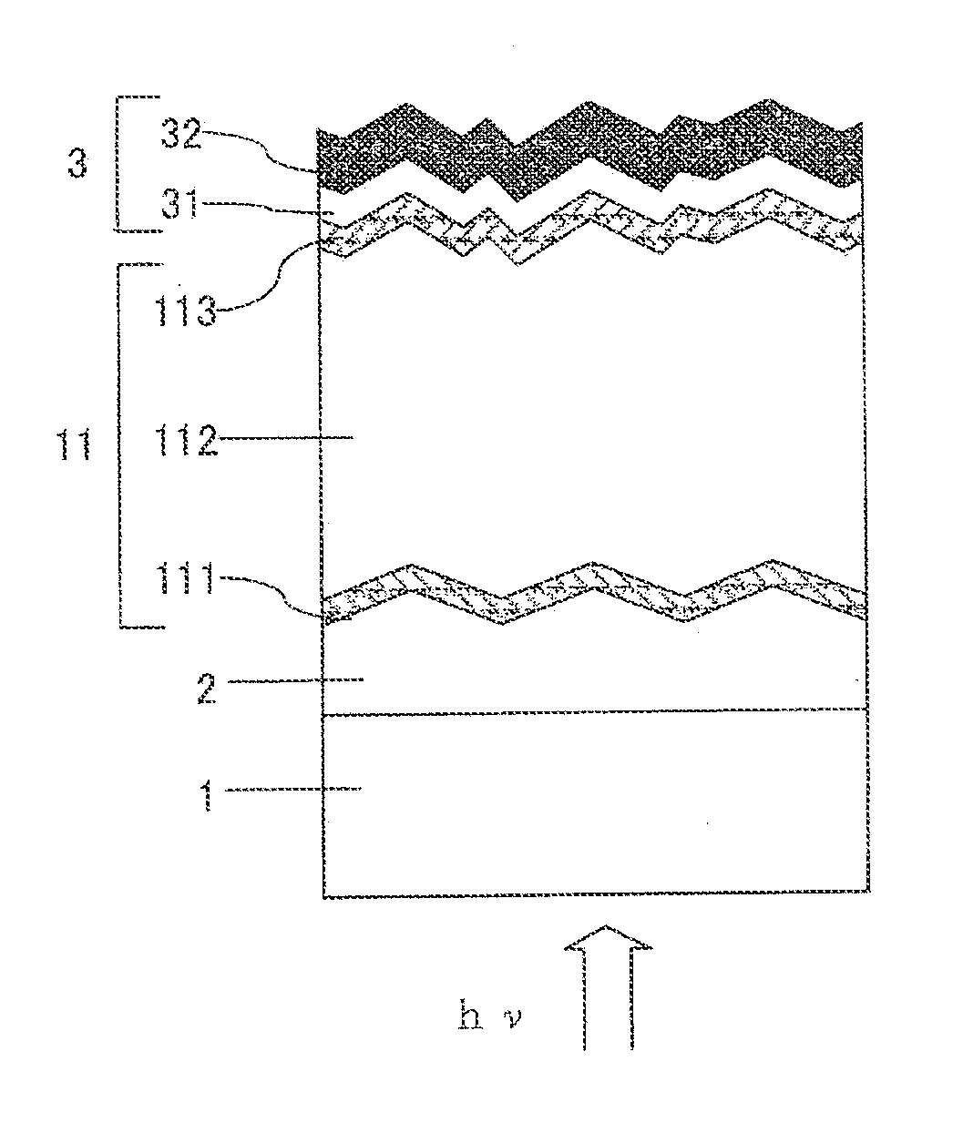
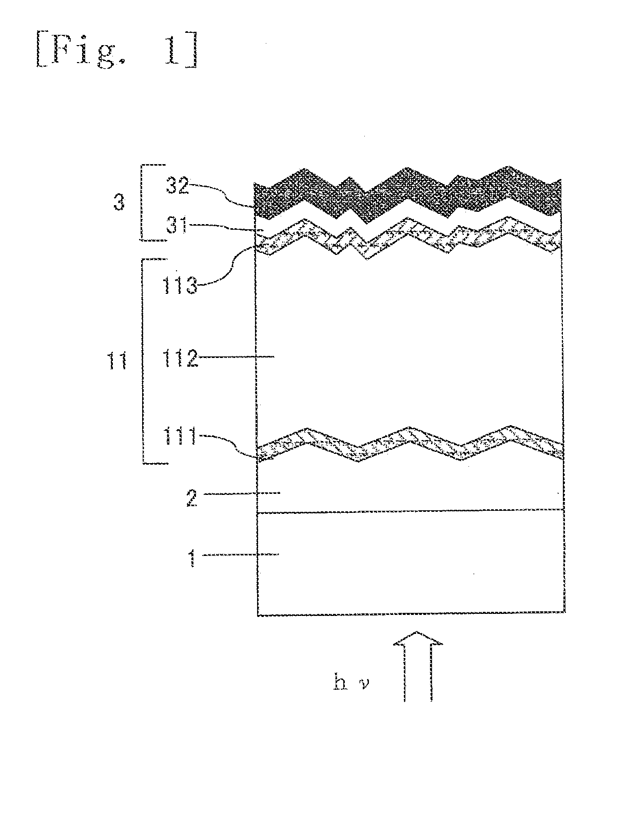
[0063]As Example 1, a transparent electrode was formed on a glass substrate, and a substrate having a transparent electrode for a thin film solar cell was prepared for preparing a thin film solar cell shown in FIG. 1.

[0064]A glass substrate having a thickness of 5 mm and a 125 mm square size was used as a transparent insulating substrate 1, and B-doped ZnO film was deposited thereon as a transparent electrode 2 in a thickness of 2.0 μm using a low-pressure thermal CVD method. The transparent electrode 2 was formed by a CVD method under reduced-pressure conditions while feeding, as raw material gases, diethylzinc (DEZ) and water into a reaction chamber by a direct vaporization process and feeding, as a dopant gas, diborane gas diluted to 0.5% with hydrogen at a substrate temperature of 160° C. The flow ratio of water and DEZ was 2.8, and the flow ratio of diborane and DEZ was 0.25% (DEZ:diborane diluted with hydrogen=2:1).

example 2

[0065]Also in Example 2, a substrate having a transparent electrode for a thin film solar cell was prepared in the same manner as in Example 1, but unlike Example 1, the substrate temperature during deposition of the ZnO film was changed to 165° C. and the flow ratio of water / DEZ was changed to 3.

example 3

[0066]Also in Example 3, a substrate having a transparent electrode for a thin film solar cell was prepared in the same manner as in Example 1, but unlike Example 1, the ZnO film was deposited in a thickness of 2.2 μm.


PUM


Abstract

Disclosed are: a transparent electrode having a zinc oxide film wherein initial characteristics and humidity resistance during long-time use coexist; and a thin film solar cell provided with said electrode. The transparent electrode contains a transparent conductive layer mainly made of zinc oxide. The transparent conductive film preferably has the following characteristics: having surface irregularities; a carrier concentration of 9×1019 cm−3 or less; a crystal structure having a (110) preferred orientation; a ratio of a (110) peak intensity to a (002) peak intensity I(110) / I(002) measured by X-ray diffraction being 50 or more; and a crystallite with a (110) orientation has a size of: 23 nm or more and 50 nm or less, in a planar direction parallel to a substrate; and 30 nm or more and 60 nm or less, in a planar direction perpendicular to the substrate.

Description

TECHNICAL FIELD[0001]The invention relates to a transparent electrode for a thin film solar cell having an improved reliability during long-time use, and a substrate having a transparent electrode for a thin film solar cell and a thin film solar cell using the same.BACKGROUND ART[0002]Recently, as a measure against problems of environmental pollution and global warming, solar cells have been actively researched and developed, and increasingly introduced as a source of clean energy. Thin film solar cells are receiving prominent attention as solar cells that allow for both reduction of costs and improvement of efficiency. In particular, methods of forming a high-quality semiconductor layer on an inexpensive substrate such as glass using a low-temperature process is expected to be capable of achieving cost reductions.[0003]“Light confinement” has been put into practical use in which a surface of a transparent conductive film, which contacts a light incident side of a photoelectric conv...

Claims


Application Information

Patent Timeline
IPC IPC(8): H01L31/0224H01L31/18
CPCH01L31/022483Y02E10/50H01L31/1884
Inventor TAWADA, YUKOFUJIBAYASHI, TAKASHI
Owner KANEKA CORP
Learn More