Manufacture Method for a Surface Mounted Power LED Support and its Product

a manufacturing method and power led technology, applied in the direction of manufacturing tools, lighting and heating equipment, lighting support devices, etc., can solve the problems of poor universal applicability of ordinary insulating boards and low yield rate, and achieve high production efficiency, good product reliability, and simple processes

Active Publication Date: 2013-05-16
FOSHAN NATIONSTAR OPTOELECTRONICS CO LTD +1
View PDF1 Cites 9 Cited by
  • Summary
  • Abstract
  • Description
  • Claims
  • Application Information

AI Technical Summary

Benefits of technology

[0012]Compared with the prior ceramic substrate and PLCC-type bracket, an ordinary insulating board, such as a PCB board, has advantages such as a low cost, a relatively mature board manufacturing process, namely, the ordinary insulating board has such advantages as a low cost and easy to be manufactured. However, since the ordinary insulating board has disadvantages of poor heat dissipation effect and poor heat resisting property, on one hand, it is generally accepted, by the person skilled in the art, that the ordinary insulating board cannot meet the high heat dissipation property requirement of the power LED device, and thus can only be used for a small power LED device, thereby the ordinary insulating board has a poor universal applicability. On the other hand, problems, such as delamination and deformation of the board may occur in the packaging and die bonding process of the LED due to the poor heat resisting property of the ordinary insulating board, thus the yield rate is low, thereby it is generally accepted by the person skilled in the art that the ordinary insulating board is not applicable to be employed as a packaging material for the power LED.
[0013]The present application overcomes the above technical prejudice by employing an ordinary insulating board coated with metal layers on two sides thereof as a substrate for manufacturing a power LED bracket, and makes further technical innovations and improvements on the basis of the technical solution in which the single-sided copper coated circuit board is employed as the bracket substrate and is bonded with a the metal sheet, to overcome the existed technical drawbacks. According to the present application, an ordinary insulating board is employed as a substrate, with two sides of the insulating board being coated with metal layers to form a double-sided metal layer coated circuit board, and is used as the substrate for manufacturing the surface mounted power LED bracket. Then, by a regular manufacture process of the ordinary insulating board and an innovative and special design for the bracket structure, the present application can realize an object of providing a method for manufacturing a surface mounted power LED bracket and the surface mounted power LED bracket.
[0016]The present application provides a bracket structure and a method for manufacturing the bracket structure which are different from those of the prior art. The technical solutions of the present application make innovations on the manufacture process and the product structure. The present application overcomes the prior technical prejudice by employing an ordinary insulating board, with metal layers coated on both sides thereof, as a double-sided metal layer coated circuit substrate to manufacture the bracket. With the innovative design of the structure and the process of the technical solutions of the present application, and with a machining process of the ordinary insulating board and other conventional processes for manufacturing the LED bracket, the double-sided metal layer coated circuit substrate can be processed into a surface mounted power LED bracket. On one hand, the present application has simple processes, high production efficiency, good product reliability, and greatly reduces the production cost. On the other hand, with the innovative design of the bracket structure of the present application, the LED bracket made of the ordinary insulating board can meet the high heat-resistant requirement of the power LED. In the bracket structure of the present application, an LED chip directly contacts a thick metal layer which is of an integral structure, has a good heat conductivity and forms a chip mounting portion, such that heat generated by the LED chip in operation can be released to the outside directly through the thick metal layer, and thus the LED bracket has a good heat dissipation effect, a high reliability, and a good light emitting effect. It is proved through tests that, the LED bracket, made of an ordinary insulating board and with metal layers coated on both sides, has a good heat resisting property, and problems such as delamination and cracking would not occur in the die bonding process using a silver paste of the LED packaging.
[0017]Based on the above description, the method of the present application overcomes the technical prejudice generally accepted by the person skilled in the art that the ordinary insulating board cannot be employed to manufacture the power LED bracket. The ordinary insulating board is skillfully applied in the manufacture of the LED bracket, which greatly simplifies the prior manufacture process of the power LED bracket, improves the production efficiency, and reduces the production cost. The product manufactured by the method of the present application has a low cost, a high reliability, a good heat dissipation and light emitting effect, can be applied to a reflow soldering process, and is applicable to a full-automatic and batch testing and taping process, is convenient for a batch soldering and mounting of the downstream products, and is particularly convenient for the subsequent surface mounted processes of the manufacture of the LED product, and thus has a wider application range. Therefore, the present application is an invention overcoming a technical prejudice. Compared with the prior art, the method and the product of the present application achieve a notable progress and have prominent and positive advantageous technical effects.

Problems solved by technology

However, since the ordinary insulating board has disadvantages of poor heat dissipation effect and poor heat resisting property, on one hand, it is generally accepted, by the person skilled in the art, that the ordinary insulating board cannot meet the high heat dissipation property requirement of the power LED device, and thus can only be used for a small power LED device, thereby the ordinary insulating board has a poor universal applicability.
On the other hand, problems, such as delamination and deformation of the board may occur in the packaging and die bonding process of the LED due to the poor heat resisting property of the ordinary insulating board, thus the yield rate is low, thereby it is generally accepted by the person skilled in the art that the ordinary insulating board is not applicable to be employed as a packaging material for the power LED.

Method used


Image

  • Manufacture Method for a Surface Mounted Power LED Support and its Product
  • Manufacture Method for a Surface Mounted Power LED Support and its Product
  • Manufacture Method for a Surface Mounted Power LED Support and its Product

Examples


first embodiment

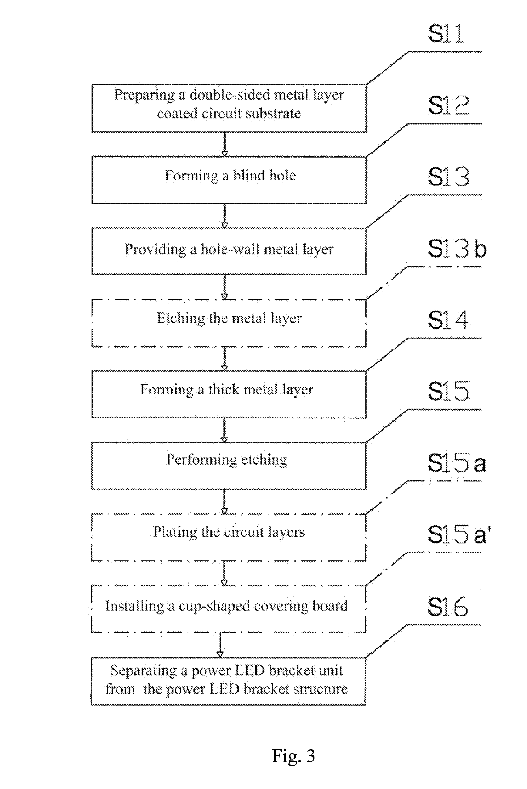
[0029]A method for manufacturing a power LED bracket according to the present application is shown in FIGS. 3 and 4. Manufacture steps of the embodiment are described in detail in conjunction with the process flow chart of the embodiment shown in FIG. 3 and the schematic view of the process steps shown in FIG. 4.

[0030]Step S11), preparing a double-sided metal layer coated circuit substrate: A double-sided metal layer coated circuit substrate 1 is prepared in advance. As shown in FIG. 4A, the circuit substrate 1 includes an ordinary insulating substrate 10, a first metal layer 11 coated on the upper surface of the substrate and a second metal layer 12 coated on the lower surface of the substrate 10. There is no special requirement on the material of the substrate 10. The substrate may be an ordinary insulating board such as a PCB board. Preferably, the substrate may be cheap materials, such as a fiber-glass cloth substrate, a CEM-3 (Composite Epoxy Material Grade-3) substrate, or a C...

second embodiment

[0043]A method for manufacturing a power LED bracket according to the present application is shown in FIGS. 5 and 6. Manufacture steps of the embodiment are described in detail in conjunction with the process flow chart of the embodiment shown in FIG. 5 and the schematic view of process steps shown in FIG. 6.

[0044]Step S21), preparing a double-sided metal layer coated circuit substrate: A double-sided metal layer coated circuit substrate 2 is prepared in advance. The circuit substrate 2 includes an ordinary insulating substrate 20, a first metal layer 21 coated on the upper surface of the substrate and a second metal layer 22 coated on the lower surface of the substrate. There is no special requirement on the material of the substrate 20. The substrate may be an ordinary insulating board such as a PCB board. Preferably, the substrate may be cheap materials such as a fiber-glass cloth substrate (FR-4), a CEM-3 (Composite Epoxy Material Grade-3) substrate, or a CEM-1 (Composite Epoxy ...

third embodiment

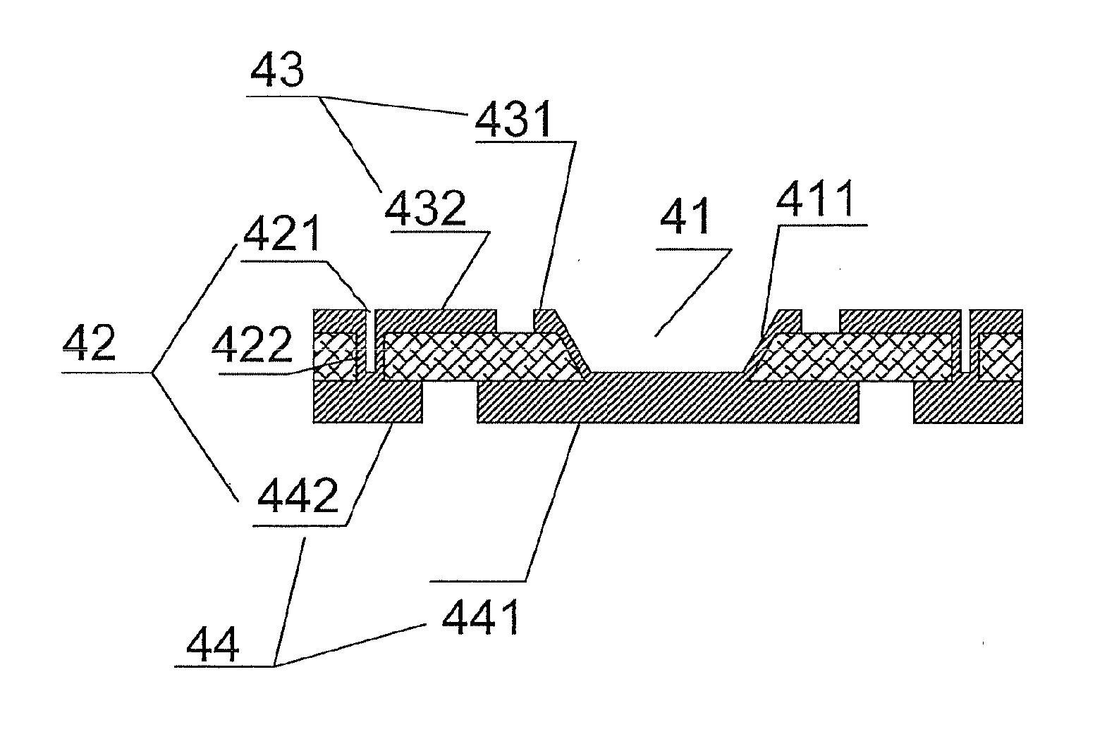
[0059]A power LED bracket according to another of the present application is shown in FIG. 10. The power LED bracket of the present embodiment differs from the power LED bracket by further including a cup-shaped covering board 45 provided on the upper surface of the bracket substrate 4. The cup-shaped covering board 45 is connected to the upper surface of the bracket substrate 4 via an adhesive film 46, and further includes a cup hole 451 corresponding to the position of the blind hole 41. A diameter of the cup hole 451 is larger than a diameter of the blind hole 41, with the lead connecting portion 431 being exposed in the cup hole 451 and the positive and negative electrode 42 being covered by the cup-shaped covering board 45. The cup-shaped covering board 45 may be of a reflection cup shape or a cylindrical shape, and is not limited to the present embodiment. In other embodiments, the upper surface of the cup-shaped covering board 45 may be coated with a black material to increa...


PUM

PropertyMeasurementUnit
thicknessaaaaaaaaaa
conductiveaaaaaaaaaa
diameteraaaaaaaaaa

Abstract

A manufacture method for a surface mounted power LED support comprises providing a wiring board having both sided metal layers. In addition, the method comprises forming a hole. Further, the method comprises setting a metal layer in the surface of the hole. Still further, the method comprises thickening the metal layer of the wiring board. The method also comprises etching the metal layer of the wiring board. Moreover, the method comprises cutting the wiring board to form single support unit. A surface mounted power LED support comprises a both sided wiring board, a hole formed in the wiring board and wiring layers set on the surface of the wiring board.

Description

CROSS REFERENCE TO RELATED APPLICATIONS[0001]This application is a 35 U.S.C. §371 national stage application of PCT / CN2010 / 076325 filed Aug. 25, 2010, which claims the benefit of Chinese Patent Application No. 201010191873.7 filed Jun. 4, 2010 and Chinese Patent Application No. 201020215719.4 filed Jun. 4, 2010, each of which is hereby incorporated herein by reference in its entirety for all purposes.STATEMENT REGARDING FEDERALLY SPONSORED RESEARCH OR DEVELOPMENT[0002]Not applicable.TECHNICAL FIELD OF THE INVENTION[0003]The present application relates to a method for manufacturing an LED bracket applicable to an LED device and the LED bracket, in particular, to a method for manufacturing a surface mounted power LED bracket and the surface mounted power LED bracket.BACKGROUND OF THE INVENTION[0004]The semiconductor illumination is known as the fourth generation of illuminating source, and is gradually applied to the general illumination field. The power light emitting diode (power LE...

Claims


Application Information

Patent Timeline
Patent Type & Authority Applications(United States)
IPC IPC(8): F21V21/00B23P11/00
CPCH01L33/486H01L33/62B23P11/00F21V21/00H01L2224/48247H05K2201/0394Y10T29/49996H05K1/183H01L2933/0033H01L2933/0066H05K2201/10106H01L2224/48091H01L2924/00014H01L33/48
Inventor YU, BINHAISUN, BAIRONGLI, WEIPINGXIA, XUNLILI, CHENGLONG, MENGHUALIANG, LIFANG
Owner FOSHAN NATIONSTAR OPTOELECTRONICS CO LTD
Why Eureka
Try Eureka