
Low-cost microbial habitat for water quality enhancement and wave mitigation

a microbial habitat and low-cost technology, applied in pisciculture, aquaria, marine site engineering, etc., can solve the problems of increasing the cost of manufacture and deployment, inherently unstable background art floating platforms, and excessive bob and rock of existing floating platforms, so as to achieve less material mass, less material cost, and enhanced stability

Inactive Publication Date: 2013-05-23
FOUNTAINHEAD
View PDF0 Cites 26 Cited by
  • Summary
  • Abstract
  • Description
  • Claims
  • Application Information

AI Technical Summary

Benefits of technology

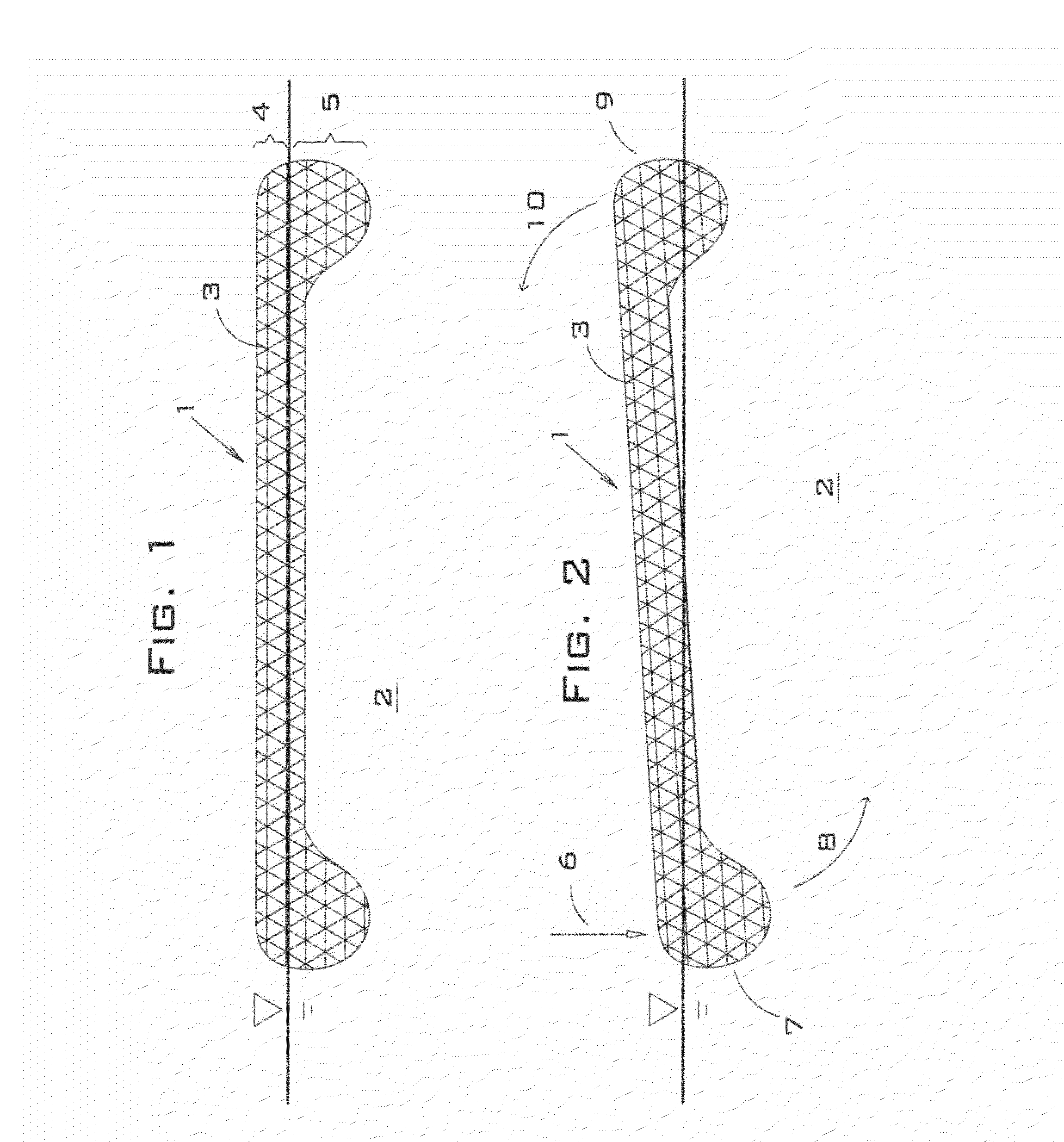
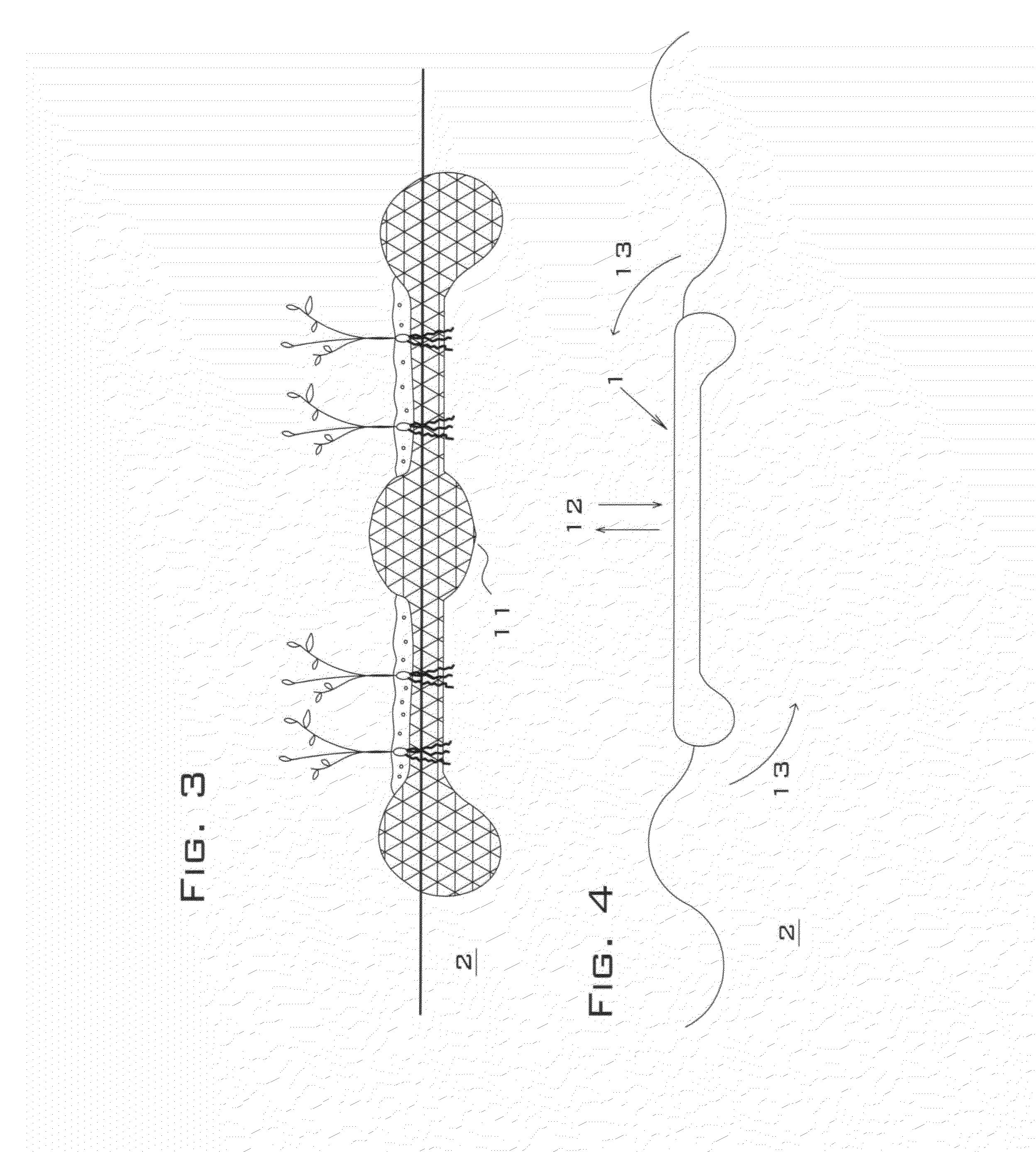
The present invention provides a high-capacity microbial habitat with tip-resistance and wave damping for floating islands and submerged structures. The invention uses the weight of trapped water and / or strategically positioned negatively buoyant materials and water-produced drag to counter tipping forces, which provides enhanced stability with significantly less material mass than background art designs. The invention can also be made smaller and less costly than existing designs with comparable stability against wave-induced motion. The islands can also be used to support water aerators or water circulators for increasing dissolved oxygen concentration in the water body and maintaining high growth rates of fish and aquatic insects.

Problems solved by technology

First, background art floating platforms are inherently unstable against tipping when a load is placed near their perimeter (for example, a human swimmer climbing onto a floating dock tends to tilt and submerge the edge of the platform where he is attempting to board).
Second, existing-art floating platforms tend to bob and rock excessively when waves are present.
Existing designs typically must be oversized to counter these motions, which increases the costs of manufacture and deployment.
Third, existing designs do not integrate high levels of inexpensive scrap polymers to provide high levels of surface area for colonization by beneficial microbes, which in turn convert pollution-causing nutrients to biomass and nitrogen gas.

Method used


Image

  • Low-cost microbial habitat for water quality enhancement and wave mitigation
  • Low-cost microbial habitat for water quality enhancement and wave mitigation
  • Low-cost microbial habitat for water quality enhancement and wave mitigation

Examples


first embodiment

[0187]In a first embodiment, a simulated coral reef is constructed from a buoyant polymer matrix structure that is anchored at or near the bottom of a water body. This embodiment may be advantageous for locations in which floating water-treatment structures are undesirable (for example, in zones of boat traffic). Although the simulated coral reefs may be constructed from either polymer (e.g., polyester, polyethylene, or polypropylene) or natural fibers (e.g., coir, jute, or tree branches), polymer materials are generally preferred over natural materials for biofilm substrates in natural water systems because natural fibers provide a source of organic carbon for microbial biofilms that grow on the fibers, and the biofilm communities growing on natural materials tend to be dominated by microbes (such as bacteria) that require organic carbon for metabolism. When these microbes metabolize the organic carbon in the natural fibers, they also uptake dissolved oxygen from the water and disc...

second embodiment

[0196]A second embodiment is shown in FIG. 15. In this embodiment, a positively or negatively buoyant simulated coral structure 101 is fabricated from one or more pieces of polymer matrix 112 and / or one or more permeable bag units 113 that are strung together vertically via a connecting rod 111 that passes through each piece of polymer matrix 112 and / or permeable bag unit 113. The lower end of the connecting rod 111 is attached to an anchor assembly 103 that positions the simulated coral structure 101 above the water body bottom 102 at a pre-determined height.

[0197]Each piece of polymer matrix 112 may alternately be comprised of polyester fibers reinforced with latex binder or recycled carpet fibers bonded into a permeable mat. Each permeable bag unit 113 is comprised of a containment bag made of netting filled with scrap pieces of polymer matrix, loose polymer fibers, or a combination of scrap matrix and loose fibers. Each of the pieces of polymer matrix 112 and permeable bag units...

fourth embodiment

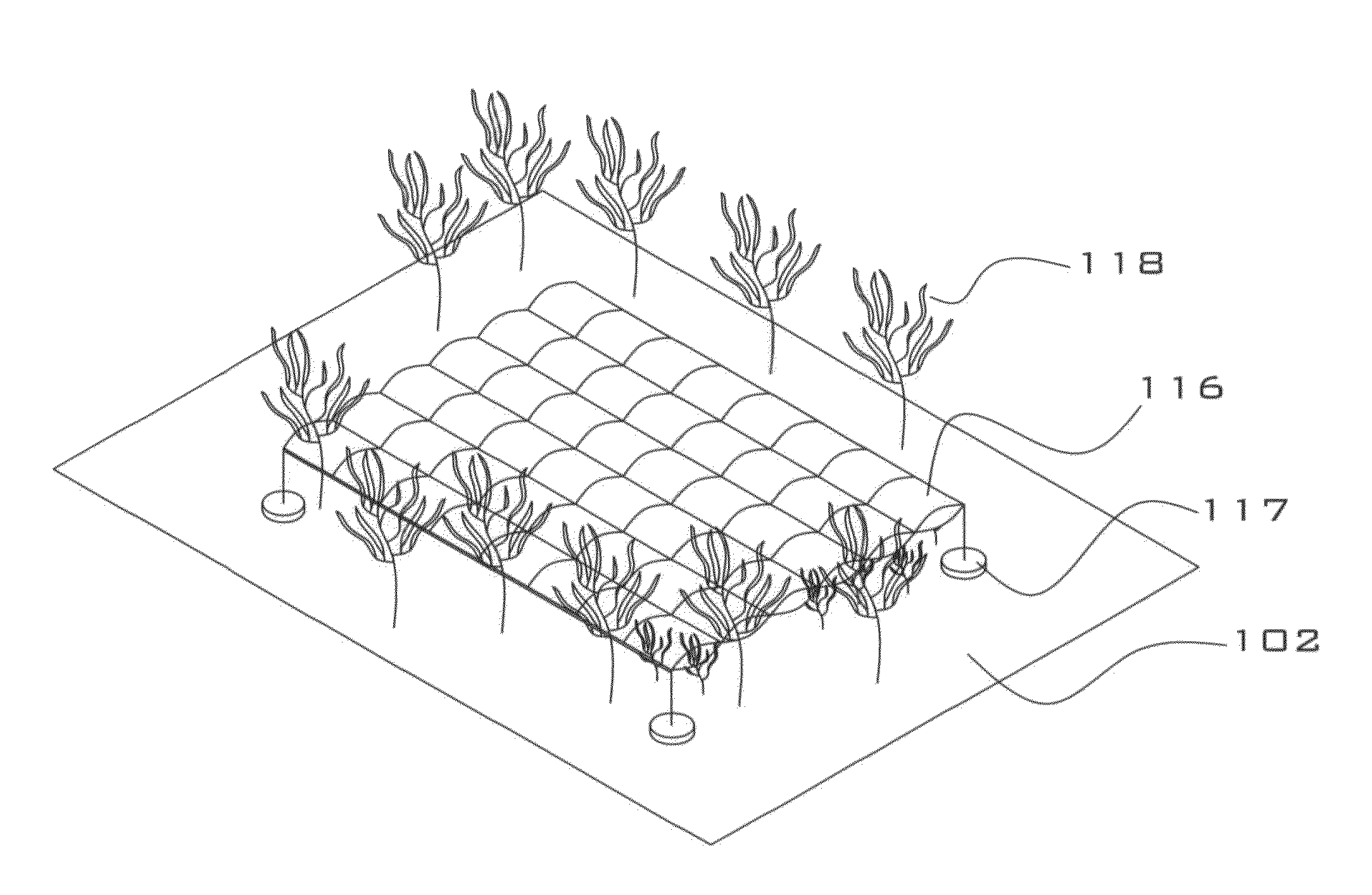
[0200]the present invention is shown in FIG. 17. In this embodiment, a weed blanket 116 is suspended above a lake bottom 102 by anchor weights 117 placed around the perimeter of the weed blanket 116. The weed blanket 116 shown in FIG. 17 is comprised of polymer fibers that are sandwiched between two layers of permeable fabric. Alternately, the weed blanket may be comprised of sheets of polymer matrix material (not shown). When the weed blanket 116 is installed over submerged aquatic plants 118, the weed blanket 116 prevents sunlight from reaching the plants 118 that are beneath the weed blanket 116, thereby causing these plants 118 to die and also preventing new plant growth. The weed blanket 116 may optionally be shaped so as to form a long, narrow bottom covering (for example, 15 feet wide by 100 feet long). This shape is particularly advantageous for providing weed-free pathways for boat traffic in lakes with prolific weed growth.

[0201]The weed blanket may be designed to be negat...


PUM


Abstract

A simulated coral reef comprising a polymer matrix body comprised of sheets of permeable and porous nonwoven polymer fiber matting, outwardly extending deployment connectors, and anchor connectors that connect the matrix body to an anchor assembly. A simulated coral reef comprising pieces of polymer matrix and / or permeable bag units strung together vertically by a connecting rod attached to an anchor assembly. A simulated coral reef comprising pieces of polymer matrix, permeable bag units, and surface attachment structures in which the pieces of polymer matrix and permeable bag units are attached to the surface attachment structures by a connecting cable. A simulated coral reef comprising a weed blanket fully submerged in a water body and suspended over the bottom of the water body. A simulated coral reef comprising hanging curtains suspended from asurface attachment structure. A simulated coral reef comprising sheets of permeable polymer matrix attached to a rigid metal frame.

Description

CROSS-REFERENCE TO RELATED APPLICATION[0001]This application is a continuation-in-part of U.S. patent application Ser. No. 12 / 523,733 filed on Jul. 19, 2009, which in turns claims priority back to U.S. Patent Application No. 60 / 887,802, filed on Feb. 1, 2007.BACKGROUND OF THE INVENTION[0002]This invention relates to low-cost, man-made structures for use in water. In particular, the invention relates to concentrated surface area, tip-resistant and wave damping floating islands and negatively buoyant structures.[0003]Background art floating platforms are deployed for a wide variety of applications. Floating docks are used by human swimmers for resting and diving. Floating wildlife rafts are used to provide nesting and resting habitat for birds, mammals, reptiles and amphibians. Floating water treatment platforms are used to grow plants and microbes that uptake and convert water-borne contaminants such as excess nutrients and dissolved metals.[0004]All of the structures described above...

Claims


Application Information

Patent Timeline
IPC IPC(8): E02B3/04A01K61/00
CPCA01K61/006E02B3/046A01K61/70Y02A10/26Y02A40/81
Inventor KANIA, BRUCE G.STEWART, FRANK M.
Owner FOUNTAINHEAD
Learn More