Luminescent solar concentrator and method for making the same,

a technology of solar concentrator and light source, applied in the field of light source, can solve the problems of loss, not hitting the waveguide surface at an angle to satisfy total internal reflection, and approximately one quarter of the light generated within a prior arc lsc, etc., and achieves the effect of enhancing the proportion of light incident, high efficiency, and enhancing the proportion of emitted ligh

Inactive Publication Date: 2013-05-23
THE UNIV OF SYDNEY
View PDF1 Cites 2 Cited by
  • Summary
  • Abstract
  • Description
  • Claims
  • Application Information

AI Technical Summary

Benefits of technology

[0021]In a second aspect of the invention, there is provided a light guide having light absorption and emission properties, wherein the angular dependence of the light emission enhances the proportion of the emitted light that is guided within the light guide.
[0022]In an embodiment, the angular dependence of the light absorption may be different than the angular dependence of the light emission. The angular dependence of the light absorption may enhance the proportion of a light incident on the light guide that is absorbed. The light guide may comprise a plurality of light emitting centers that emit light after being energized. The light guide may comprise a plurality of light absorbing centers that each absorb light incident on the light guide and transfer at least some of the energy of the absorbed light to one of the light emitting centers and so energise it. Each of the absorbing centers may have two dipoles that are orthogonal and are degenerate in energy. The dipoles may be electronic transition dipoles. The absorbing centers may each have at least one of: D4h symmetry; symmetry higher than D4h; cubic symmetry, and spherical symmetry. The emitting centers may have a long axis and emit light from only one optical transition dipole located on the long axis. The transfer of at least some energy may happen with high efficiency. The transfer of the at least some energy may be via one of Förster resonance energy transfer (FRET), ISC, TET, DEXTER, IC, and rISC.

Problems solved by technology

Approximately one quarter of the light generated within a prior arc LSC, however, does not hit a waveguide surface at an angle to satisfy total internal reflection and is lost.

Method used


Image

  • Luminescent solar concentrator and method for making the same,
  • Luminescent solar concentrator and method for making the same,
  • Luminescent solar concentrator and method for making the same,

Examples


Embodiment Construction

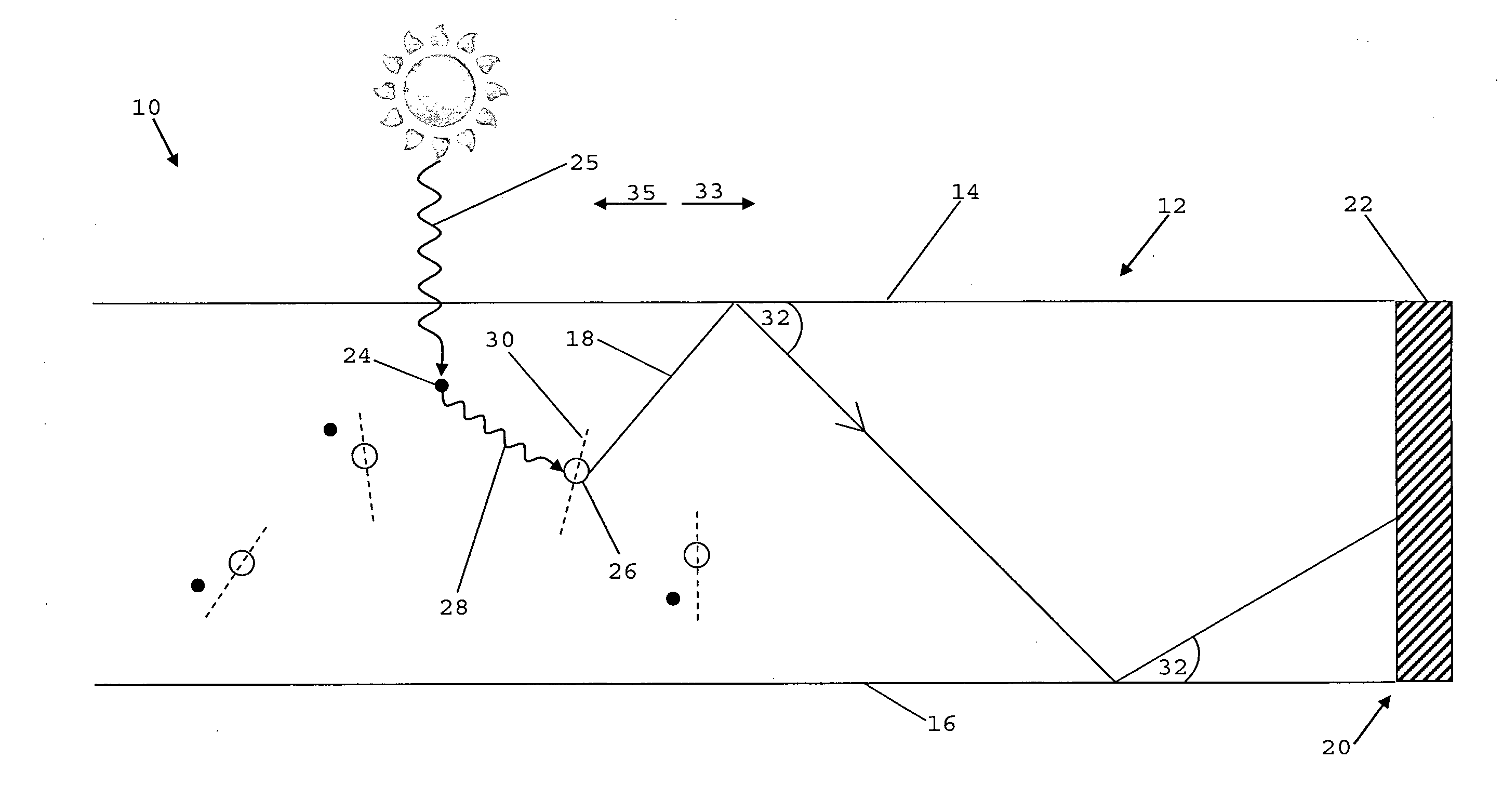
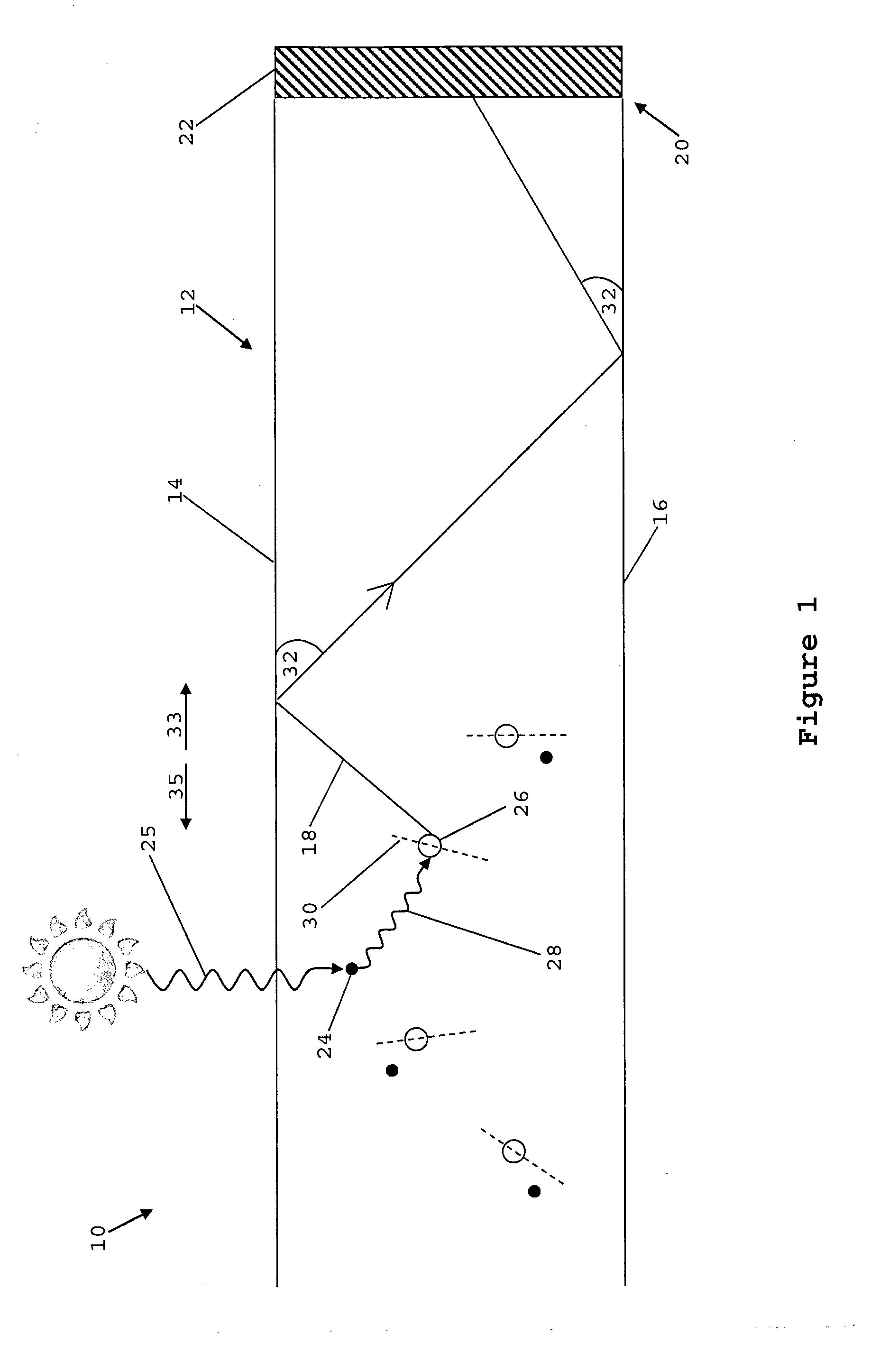
[0049]FIG. 1 is a cross sectional view of an embodiment of a luminescent solar concentrator (LSC) generally indicated by the numeral 10. The LSC comprises a light guide 12, in this embodiment in the form of a slab of Poly(methyl methacrylate) or PMMA for short. In this embodiment, but not necessarily all embodiments, the slab is surrounded by a gas, specifically air, which has a significantly lower refraction index (nair˜1.0) than the PMMA (NPMMA˜1.4). Alternatively, the slab may be clad with a material of relatively low refractive index. The top 14 and bottom 16 surfaces of the slab 12 reflect, by way of total internal reflection at the PMMA / air interface, a ray of light such as that indicated by the numeral 18 back into the guide 12. Thus, the top 14 and bottom 16 surfaces each act as a reflector. Some rays such as that indicated by the numeral 18 will thus be guided towards an end 20 of the guide 12 at which a photovoltaic cell 22 is located. The ray of light 18 is absorbed by th...


PUM

PropertyMeasurementUnit
thickaaaaaaaaaa
energyaaaaaaaaaa
total internal reflectionaaaaaaaaaa

Abstract

A luminescent solar concentrator (10) is disclosed. The luminescent solar concentrator (10) has a light guide (12) defined at least in part by a reflector (14). It has a plurality of light absorbing centers (24) located in the light guide. The light absorbing centers (24) are configured to absorb sunlight (25) instant on the light guide (12). There are a plurality of light emitting centers (26) located in the light guide (14). Each of the plurality of light emitting centers (26) are capable of emitting light (18) after at least some of the energy of the absorbed sunlight (25) is transferred (28) from a respective one of the light absorbing centers (24). Each of the plurality of light emitting centers (26) are orientated relative to the reflector (14) to enhance the proportion of light emitted by the respective light emitting center (26) that is reflected by the reflector (14) and so guided within the light guide (12).

Description

FIELD OF THE INVENTION[0001]The present invention generally relates to a light guide having light absorption and emission properties, wherein the angular dependence of the light emission enhances the proportion of the emitted light that is guided within the light guide, and particularly but not exclusively to a luminescent solar concentrator having the light guide.BACKGROUND OF THE INVENTION[0002]In a prior art luminescent solar concentrator (LSC), an ensemble of luminophores within a light guide absorb incident sunlight. The sunlight-excited luminophores then emit light approximately isotropically. Some of the light is captured by the light guide, which guides and concentrates the light to, for example, a photovoltaic (PV) cell for the generation of electricity.[0003]Approximately one quarter of the light generated within a prior arc LSC, however, does not hit a waveguide surface at an angle to satisfy total internal reflection and is lost.SUMMARY OF INVENTION[0004]According to a f...

Claims


Application Information

Patent Timeline
Patent Type & Authority Applications(United States)
IPC IPC(8): F21V8/00B05D5/06
CPCG02B6/0041H01L31/055B05D5/06Y10T156/10Y02E10/52H01L31/0547G02B6/0003
Inventor SCHMIDT, TIMOTHYMACQUEEN, ROWAN
Owner THE UNIV OF SYDNEY
Why Eureka
Try Eureka