
Vapor-liquid heat and/or mass exchange device

a mass exchange device and vapor-liquid technology, applied in the direction of heat transfer, heat transfer, lighting and heating apparatus, etc., can solve the problems of insufficient cycle implementation, increased heat and mass exchange intensity of absorber heat pump, and insufficient heat and mass exchange capacity. achieve the effect of improving flow distribution and/or heat and mass transfer

Active Publication Date: 2013-05-30
GEORGIA TECH RES CORP
View PDF8 Cites 11 Cited by
  • Summary
  • Abstract
  • Description
  • Claims
  • Application Information

AI Technical Summary

Benefits of technology

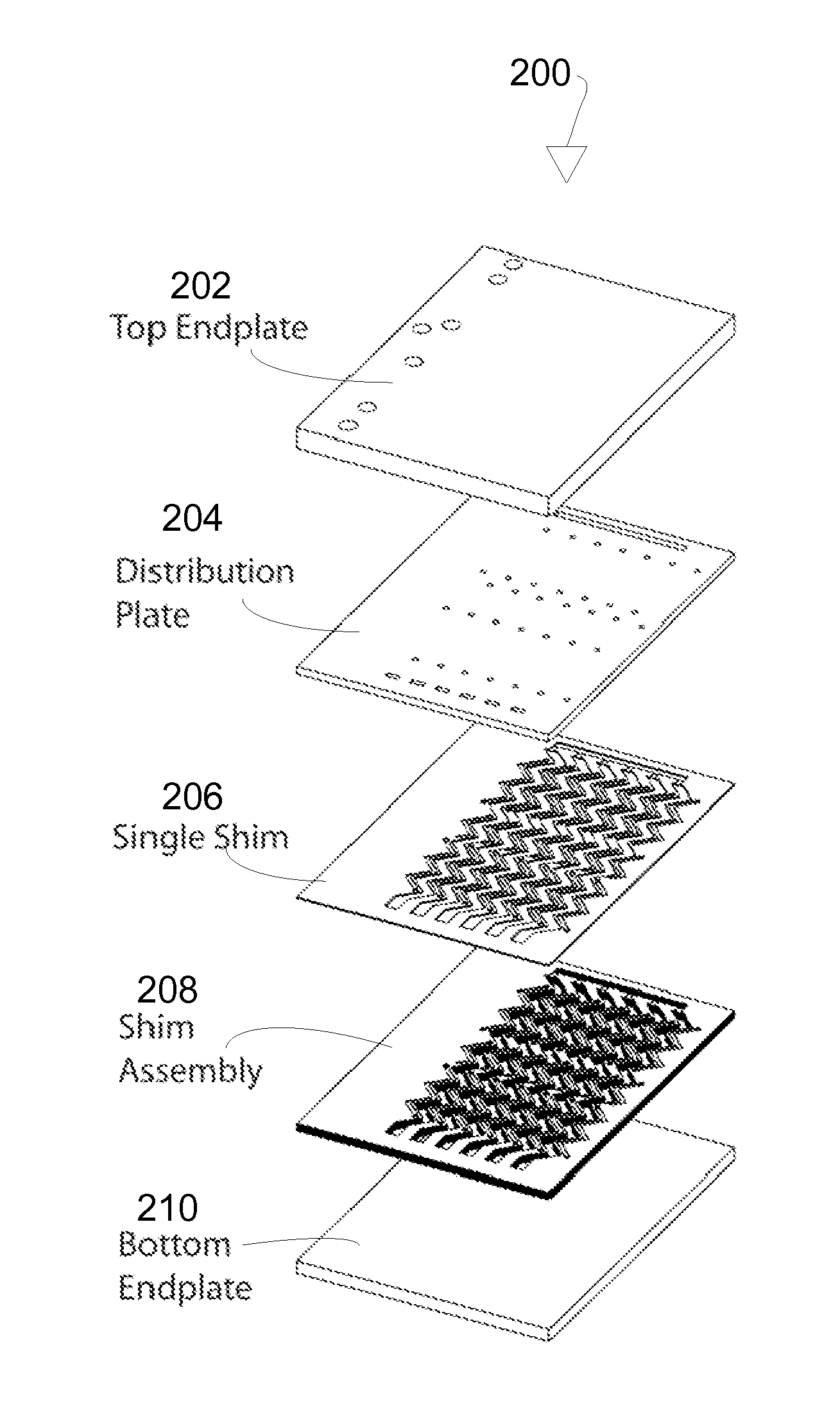
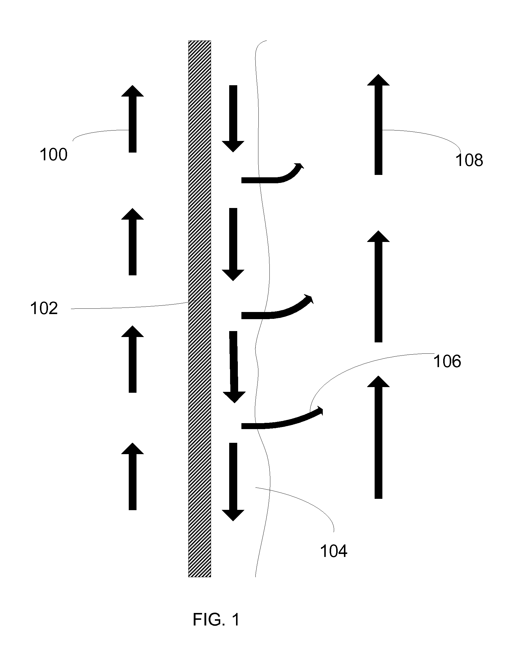
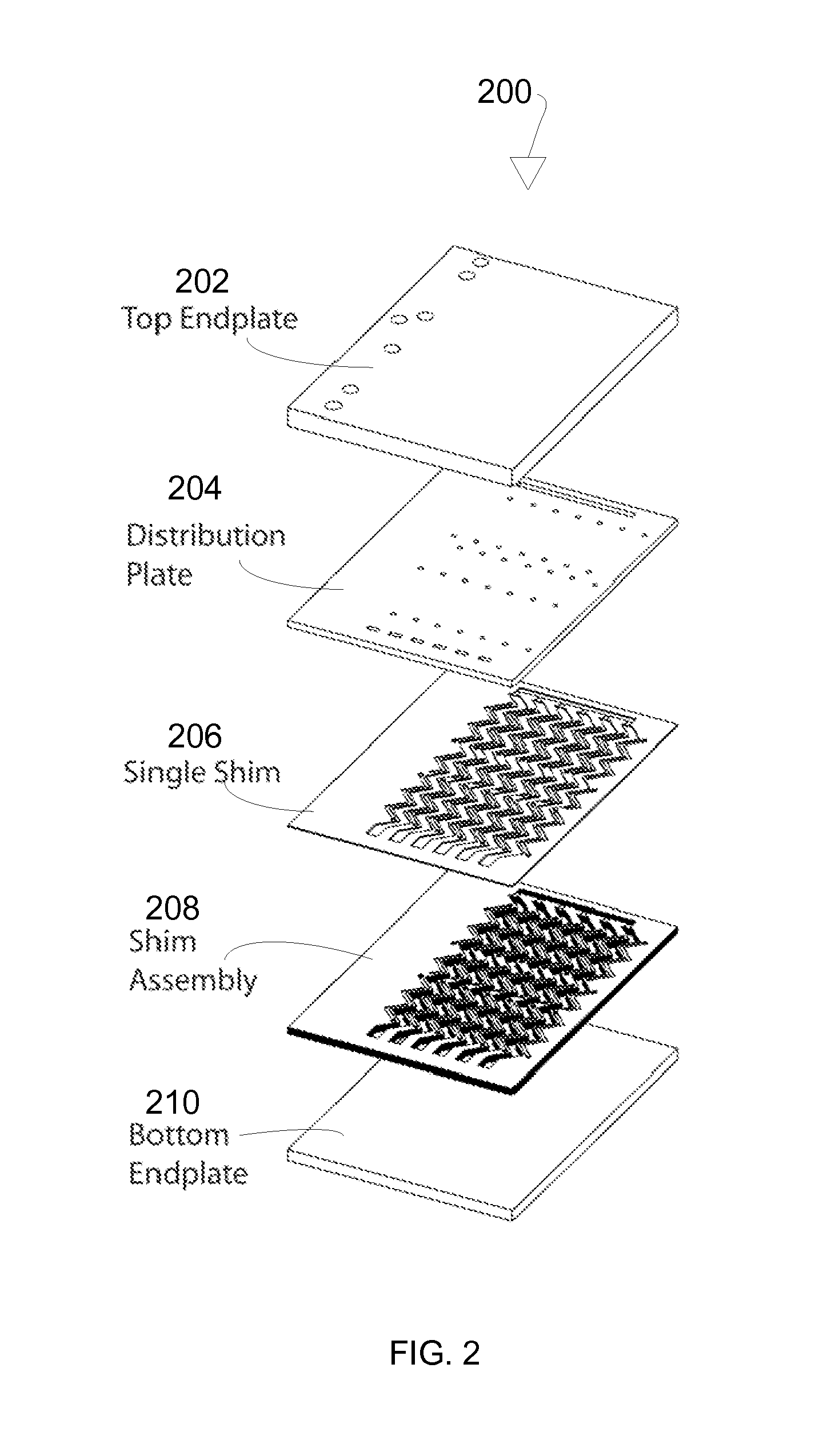
The patent describes a desorber that uses matched shims to create microchannels for heat and mass transfer. These shims can be joined to increase the desorption capabilities of the desorber, making it suitable for different applications without needing to be redesigned or re-tooled. The patent also describes various surface modification structures that can improve the flow distribution and heat and mass transfer in the fluid passage, such as dimples, elevated points, hatched surfaces, cross-hatched surfaces, and roughened surfaces.

Problems solved by technology

Since in principle the compressor of a vapor-compression system is replaced in an absorption heat pump by the combination of a desorber, an absorber, a liquid solution pump, and a recuperative solution heat exchanger, these absorption heat pumps are more heat and mass exchange intensive, requiring additional transfer surface area and / or heat and mass transfer capacity.
Achieving compact designs with small footprints while delivering high coefficients of performance (COPs) has been a major challenge thus far.
In conventional systems, these cycles have not been widely implemented, especially in small capacity or compact systems, primarily because of the lack of practically feasible and compact heat and mass exchange devices.

Method used


Image

  • Vapor-liquid heat and/or mass exchange device
  • Vapor-liquid heat and/or mass exchange device
  • Vapor-liquid heat and/or mass exchange device

Examples


Embodiment Construction

[0033]The subject matter of the various embodiments of the present invention is described with specificity to meet statutory requirements. However, the description itself is not intended to limit the scope of the claimed invention. Rather, it has been contemplated that the claimed invention can be embodied in other ways, to include different elements similar to the ones described in this document, in conjunction with other present or future technologies.

[0034]It should be noted that, as used in the specification and the claims, the singular forms “a,”“an” and “the” include plural references unless the context clearly dictates otherwise. The terms “comprising” or “containing” or “including” mean that at least the named component, element, apparatus, or method step is present in the system or article or method, but does not exclude the presence of other components, materials, apparatus, or method steps, even if the other such components, material, particles, and method steps have the ...


PUM


Abstract

The invention is directed toward a vapor-liquid heat and / or mass exchange device that can be used in an integrated heat and / or mass transfer system. To achieve high heat and mass transfer rates, optimal temperature profiles, size reduction and performance increases, appropriately sized flow passages with microscale features, and countercurrent flow configurations between working fluid solution, vapor stream, and / or the coupling fluid in one or more functional sections of the desorber are implemented. In one exemplary embodiment of the present invention, a desorber section utilizes a heating fluid flowing in a generally upward direction and a concentrated solution flowing in a generally downward direction with gravity countercurrent to the rising desorbed vapor stream. To further increase the efficiency of the system, various types of column configurations can be used. Additionally, the surfaces of the microchannels can be altered to better transfer heat.

Description

CROSS REFERENCE TO RELATED APPLICATION[0001]This application claims benefit under 35 U.S.C. §119(e) of U.S. Provisional Patent Application No. 61 / 372,213 filed 10 Aug. 2010, and entitled “Vapor-Liquid Heat and / or Mass Exchange Device”, which is incorporated by reference as if set forth herein in its entirety.TECHNICAL FIELD[0002]The present system relates generally to heat and / or mass exchange devices.BACKGROUND[0003]An absorption heat pump is an environmentally benign replacement for vapor-compression systems using synthetic refrigerants that are typically employed in residential and commercial air-conditioners, chillers and heat pumps. Unlike vapor-compression systems that utilize high-grade electrical or mechanical energy as the input that drives the system, absorption heat pumps run on more readily available and low-grade thermal energy, which can be obtained from combustion of bio-fuels and fossil fuels, from largely untapped waste heat sources, and from solar thermal energy. F...

Claims


Application Information

Patent Timeline
Patent Type & Authority Applications(United States)
IPC IPC(8): F25B15/00F28C3/06
CPCF25B15/02F25B37/00F28D9/00F28C3/06Y02B30/62F25B15/00F28D21/0015Y02A30/27F22B1/00F22B1/02F28C3/00F28C3/08F25B15/16F25B17/00F25B17/02F25B30/04F25B39/026F25B43/046F25B2315/006F25B35/02F25B35/00F28F3/12
Inventor GARIMELLA, SRINIVASDELAHANTY, JARED CARPENTERNAGAVARAPU, ANANDA KRISHNA
Owner GEORGIA TECH RES CORP
Learn More