
Device for sensing a target chemical and method of its making

a target chemical and device technology, applied in the direction of diaphragms, cells, immobilised enzymes, etc., can solve the problems of low surface roughness, damage to surrounding tissue, local decrease of ph near the electrode, etc., to avoid adhesion, surface topographical problems, and excellent adhesion to substrates. , the effect of avoiding the need for costly or time-consuming surface pretreatmen

Inactive Publication Date: 2013-06-13
MICROPEN TECH CORP
View PDF0 Cites 79 Cited by
  • Summary
  • Abstract
  • Description
  • Claims
  • Application Information

AI Technical Summary

Benefits of technology

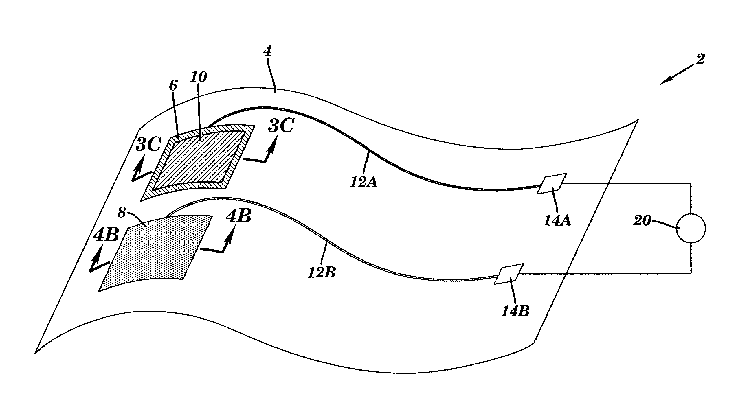
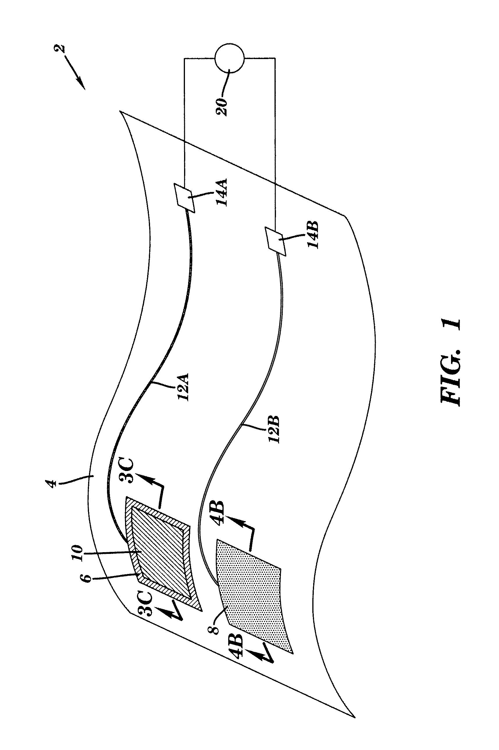
The present invention avoids adhesion and surface topographical issues, while also using conductive ink compositions for direct write dispensing. These inks have excellent adhesion properties to substrates without the need for costly or time consuming surface pretreatments. The ink composition may include a solvent that swells or dissolves the substrate and a binder that matches the mechanical properties of the substrate material and the written trace. The binder may be the same or different from the substrate material.

Problems solved by technology

If such an electrode is pulsed excessively, electrochemical reactions may occur resulting in local decreases in pH near the electrode, which in turn can damage surrounding tissue.
This results in challenges in accurate positioning, good adhesion, conformality, and low surface roughness.
However, no indication is given as to how the sensors may be affixed to the medical device after manufacture.
This sequence also requires multiple steps and poses challenges for adhesion and smoothness of the final product.
While this approach allows for the application of a sensor on a curved surface, it requires winding and adhesion of the initial wire electrode, which is cumbersome.

Method used


Image

  • Device for sensing a target chemical and method of its making
  • Device for sensing a target chemical and method of its making
  • Device for sensing a target chemical and method of its making

Examples


example 1

Measurement of Hydrogen Ion Concentration

[0067]For production of silver electrodes, polyvinyl chloride (Aldrich, high molecular weight) was dissolved in cyclohexanone at a concentration of 12% by weight, and silver flakes (Ames-Goldsmith, MBT-79) were added to bring the ratio of silver to polymer to 92:8. The total solids present in the ink composition were 63% by weight. The materials were dispersed and deaerated using a centrifugal planetary mixer (Kurabo Mazerustar model KK-50S).

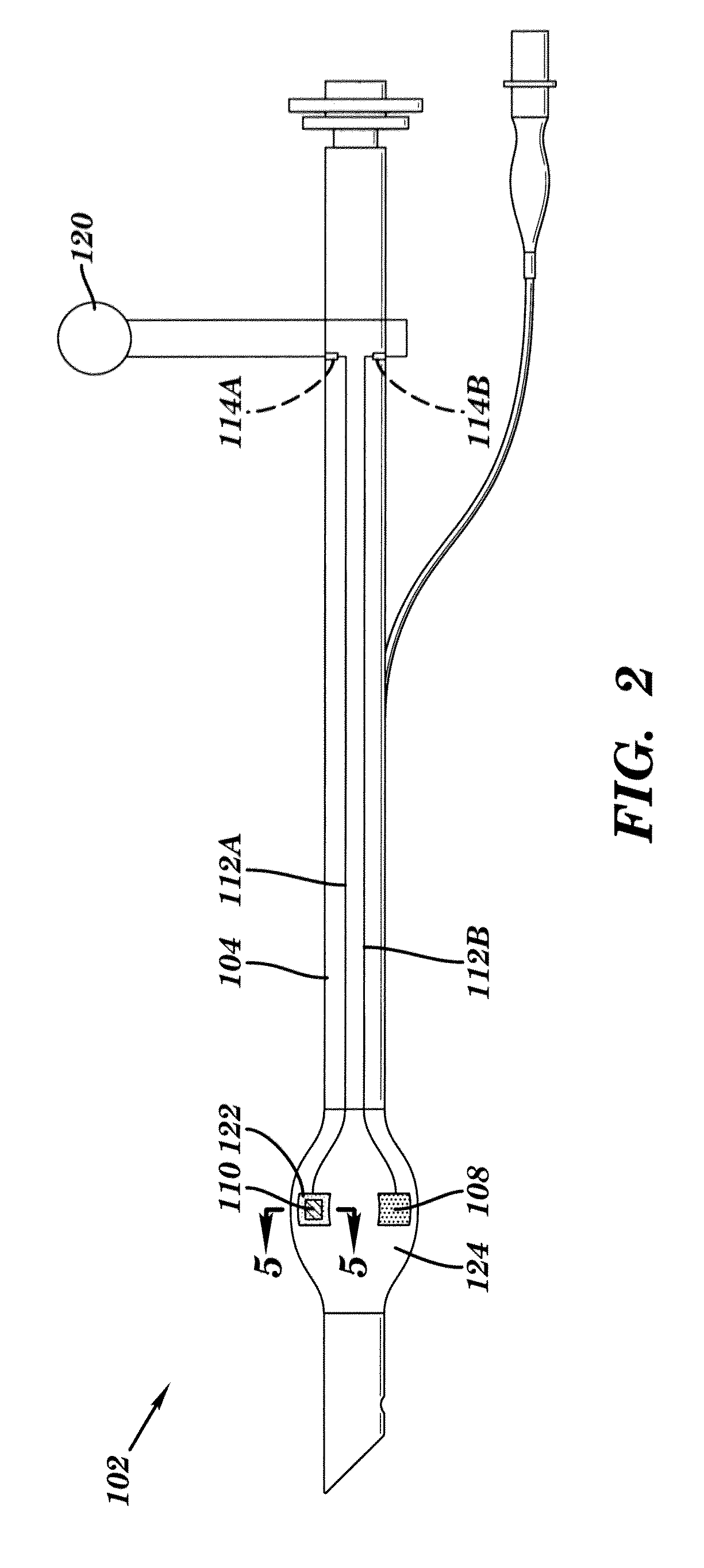
[0068]The ink was loaded into a syringe and extruded through a Micropen dispensing apparatus onto the surface of a commercially available standard endotracheal tube (Unomedical Air Management, Magill, HVLP cuff) to yield four square-shaped electrodes situated on the surface of the cuff. The electrodes were extended with a narrower written trace down the tube for a length of approximately 10 cm to allow for subsequent interconnection with external devices. The ink was cured by forced air, at 130° C., for 1...


PUM

PropertyMeasurementUnit
Thicknessaaaaaaaaaa
Thicknessaaaaaaaaaa
Flexibilityaaaaaaaaaa

Abstract

The present invention relates to a device for sensing a target chemical. The device includes a flexible, non-planar substrate; a printed, solid-state sensing element comprising a chemical sensing material which produces an electrical signal upon interaction with the target chemical; a first printed electrode comprising a first conductive composition; and a second electrode comprising a second conductive composition. The first and second electrodes are electrically isolated from one another, and one or both of the first and second electrodes is in electrical contact with said sensing element. The first and second electrodes and the sensing element collectively form an electrochemical sensor which is coupled to the flexible, non-planar substrate. Medical devices comprising the device of the present invention and methods of making a device for sensing a target chemical are also disclosed.

Description

[0001]This application claims the benefit of U.S. Provisional Patent Application Ser. No. 61 / 569,035, filed Dec. 9, 2011, which is hereby incorporated by reference in its entirety.FIELD OF THE INVENTION[0002]The present invention relates to a device for sensing a target chemical and a method of fabricating this device.BACKGROUND OF THE INVENTION[0003]Often there is a need to detect the presence of and / or quantify the level of various species in biological systems in order to study and understand chemicals necessary for optimal biological function. Ideally, chemical sensors can be positioned on medical devices so that procedures and measurements may be simultaneously executed, and further invasive operations avoided. Chemical sensors can be based on colorimetric or optical responses. However, in those cases sensitive detectors must be included in close proximity to the sensor or, alternatively, the sensor must be removed from the biological environment in order to take a measurement....

Claims


Application Information

Patent Timeline
IPC IPC(8): G01N27/30A61M16/04A61B5/00H04R25/00A61B5/1473A61B5/1477
CPCG01N27/30A61B5/14539A61B5/1477A61B5/6852A61B5/6853A61B5/6862A61B5/686A61B5/6821H04R25/00A61M16/04A61B5/6811A61B5/6812A61M16/0434A61M2205/0244A61M2205/3324G01N27/4167A61B5/1473
Inventor SHAW-KLEIN, LORI J.
Owner MICROPEN TECH CORP
Learn More