Gas-solids separation units and methods for the manufacture thereof

a technology of gas-solid separation and separation units, which is applied in the direction of water supply installations, separation processes, drawing-off water installations, etc., can solve the problems of considerable erosion within the separator cyclone barrel

Active Publication Date: 2013-06-20
UOP LLC
View PDF4 Cites 38 Cited by
  • Summary
  • Abstract
  • Description
  • Claims
  • Application Information

AI Technical Summary

Problems solved by technology

In particular, it has been observed that, over the course of continuous operation over a prolonged time period on the order of several years, considerable erosion may occur within the separator cyclone barrel.
If sufficiently severe, such erosion may require localized repair or replacement of the entire cyclonic separator, which may necessitate shutdown of the TSS and possibly the FCC system as a whole.

Method used


Image

  • Gas-solids separation units and methods for the manufacture thereof
  • Gas-solids separation units and methods for the manufacture thereof
  • Gas-solids separation units and methods for the manufacture thereof

Examples


Embodiment Construction

[0013]The following Detailed Description is merely exemplary in nature and is not intended to limit the invention or the application and uses of the invention. Furthermore, there is no intention to be bound by any theory presented in the preceding Description of Related Art or the following Detailed Description.

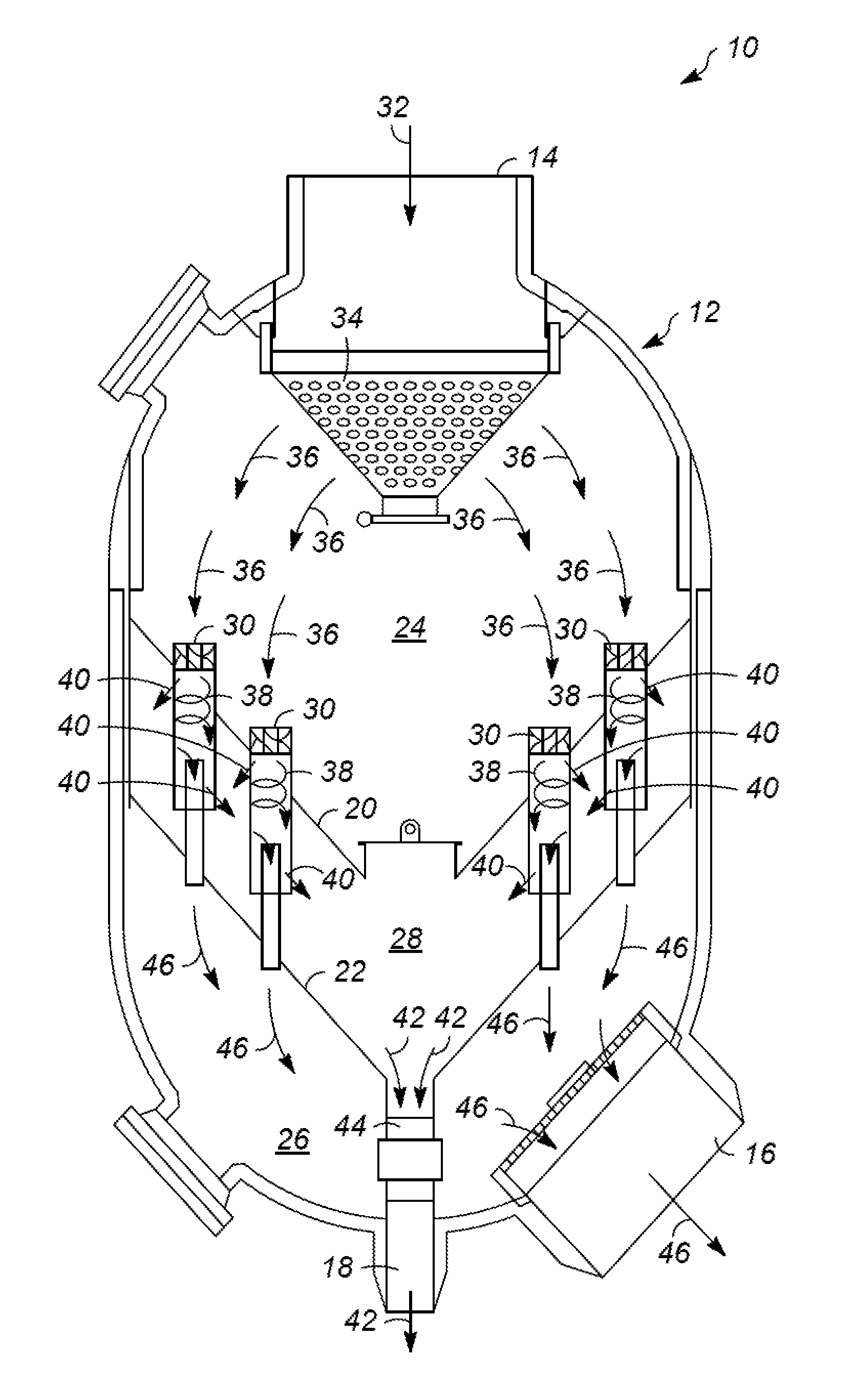
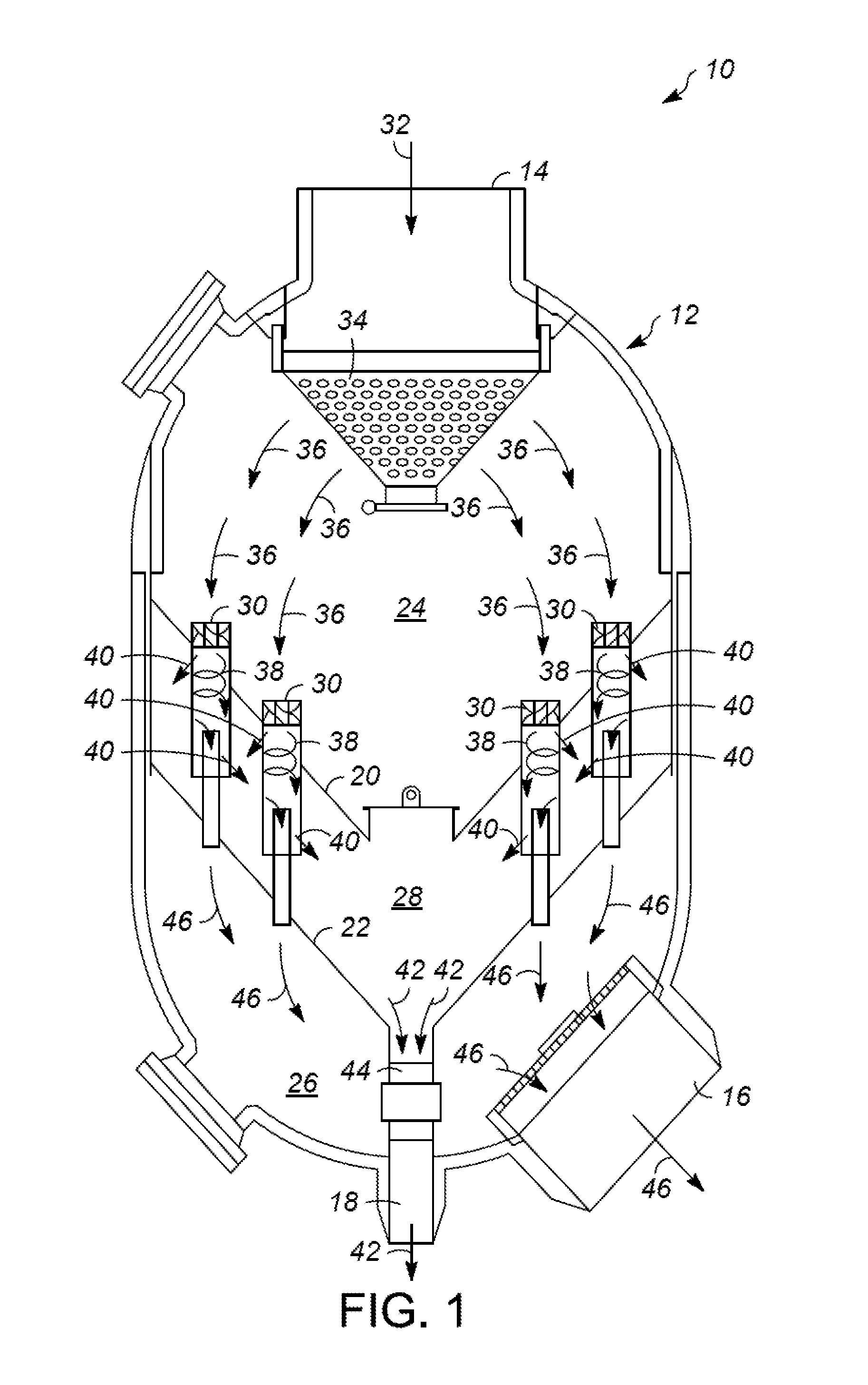
[0014]FIG. 1 is a simplified cross-sectional view of a gas-solids separation unit 10 illustrated in accordance with an exemplary embodiment of the present invention. During operation, gas solids separation unit 10 removes particulate matter entrained in a gas stream to, for example, reduce the quantity of particulate matter exhausted to the atmosphere and / or to minimize erosion of downstream equipment, such one or more turbines included within a power recovery expander unit. Gas solids separation unit 10 is especially well-suited for usage as a separator included within a fluid catalytic cracking (“FCC”) system and, specifically, as third stage separator (“TSS”), which receiv...


PUM

PropertyMeasurementUnit
diameteraaaaaaaaaa
diameteraaaaaaaaaa
temperatureaaaaaaaaaa

Abstract

Embodiments of a gas-solids separation unit and embodiments of a method for manufacturing a separation unit are provided. In one embodiment, the separation unit includes a cyclonic separator and a vessel having a flue gas chamber, a clean gas chamber, and an entrained solids chamber between the flue gas chamber and the clean gas chamber. The cyclonic separator includes, in turn, a cyclone barrel extending from the flue gas chamber toward the clean gas chamber, a swirl vane positioned across the cyclone barrel, a gas outlet tube fluidly coupling the cyclone barrel to the clean gas chamber, and a first check valve opening formed through the barrel sidewall upstream of the gas outlet tube.The check valve opening fluidly couples the cyclone barrel to the entrained solids chamber to permit the centrifugal separation of the particulate matter from the gas stream during operation of the gas-solids separation unit.

Description

FIELD OF THE INVENTION[0001]Embodiments of the present invention relate to gas-solids separation units well-suited for usage within fluid catalytic cracking systems, as well as to methods for the manufacture of gas-solids separation units.DESCRIPTION OF RELATED ART[0002]Fluid catalytic cracking (FCC) is a widely-utilized process wherein a heavy hydrocarbon feed (e.g., raw oil) is contacted with a catalyst under elevated temperatures and pressures within a main reactor to yield lighter hydrocarbon products. During the cracking process, catalyst activity gradually decreases due to the deposition of coke on the catalyst granules. To restore catalyst activity, the spent catalyst is continually withdrawn from the main reactor through a spent catalyst standpipe and supplied to a catalyst regenerator in which combustion occurs to burn-off the coke deposits. The regenerated catalyst is then recycled to the riser of the main reactor to again contact the heavy hydrocarbon feed and repeat the ...

Claims


Application Information

Patent Timeline
Patent Type & Authority Applications(United States)
IPC IPC(8): B01D45/16B23P11/00
CPCB01D45/16B04C2003/006B04C3/06B04C3/04Y10T137/0402
Inventor BRANDNER, KEVIN J.HEDRICK, BRIAN W.
Owner UOP LLC
Why Eureka
Try Eureka